Method and system to distribute high-energy pulses to multiple channels

a high-energy pulse and distribution system technology, applied in the direction of spark plugs, machines/engines, mechanical equipment, etc., can solve the problems of increased misfiring, increased unburned hc emissions, and inability to adjust individual cylinder timing variations, so as to improve the detection efficiency of photo diodes to spark emission and minimize the response to residual laser emission

Inactive Publication Date: 2010-04-20
UCHICAG ARGONNE LLC
View PDF12 Cites 9 Cited by
  • Summary
  • Abstract
  • Description
  • Claims
  • Application Information

AI Technical Summary

Benefits of technology

[0014]In accordance with features of the invention, the distributor is capable of handling laser fluencies greater than 1 MW / cm2, and is generally durable and vibration insensitive having generally low-cost and a time response smaller than 7 ms.
[0016]In accordance with features of the invention, a dichroic beam splitter is positioned in the laser beam to transmit the laser radiation while it reflects radiation at substantially all other wavelengths. A significant portion of the white light that results due to spark creation is collected by the sapphire lens of the laser plug and is collimated. The collimated beam in turn is routed by the mirror and dichroic onto a short response photo diode, such as a 1 ns response photo diode. To improve the detection efficiency of the photo diode to spark emission while minimizing the response to residual laser emission, the collimated beam is routed through a set of optical filters and a positive lens, such as a set of magenta optical filters and a positive lens.

Problems solved by technology

Lean operation, along with high intake air pressure, results in very high charge densities at the time of ignition resulting in an insulating effect across the spark plug electrodes.
This often leads to increased misfiring with subsequent loss of fuel efficiency and increased unburned HC emissions.
The problem is how to provide laser ignition to a multi-cylinder IC engine, since such a system needs to accommodate typical multi-cylinder firing sequences, in addition to individually adjust spark timing in the individual cylinders.
The problem with such systems using rotating mirrors or prisms is that adjustment of individual cylinder timing variation is not possible.
Those using galvanometers have limited long-term durability.
Schemes using pockels cells are of high cost and poor durability.
The laser plug focuses the coherent emission from the pulsed laser to a tiny volume or focal spot and a high electric field gradient at the focal spot leads to photoionization of the combustible mixture resulting in ignition.

Method used


Image

  • Method and system to distribute high-energy pulses to multiple channels
  • Method and system to distribute high-energy pulses to multiple channels
  • Method and system to distribute high-energy pulses to multiple channels

Examples


Embodiment Construction

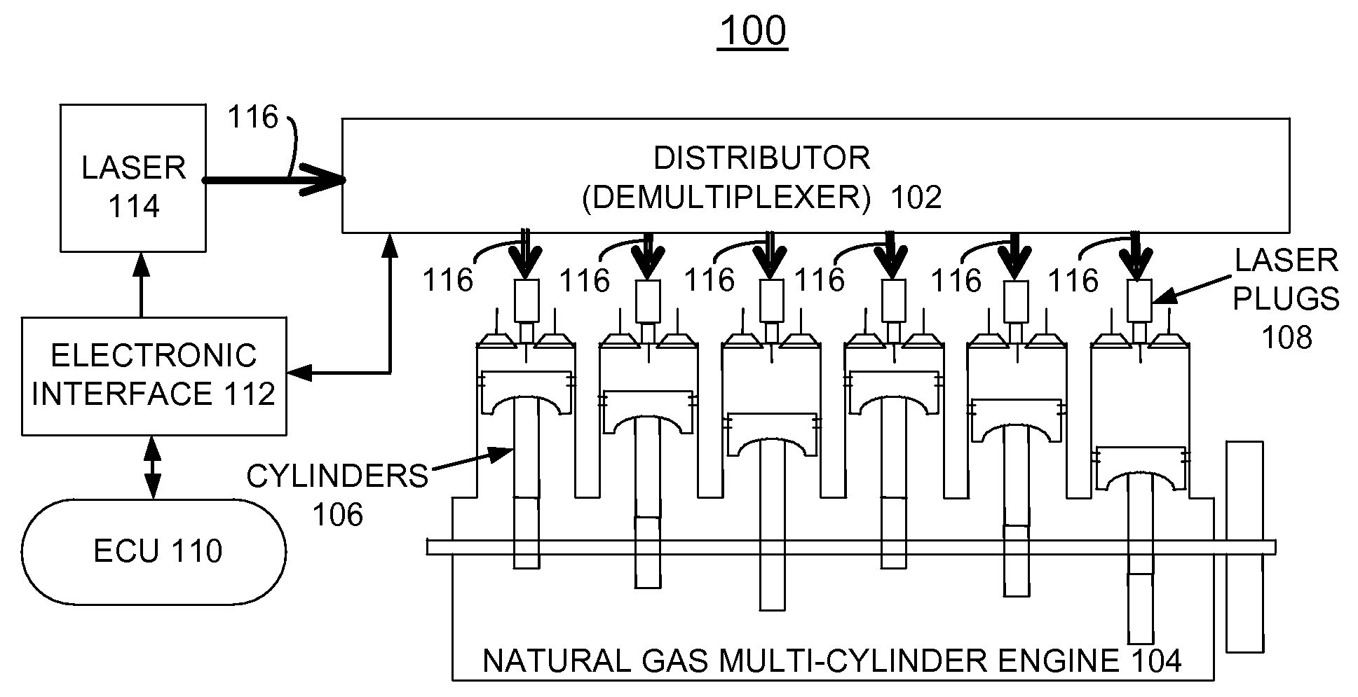
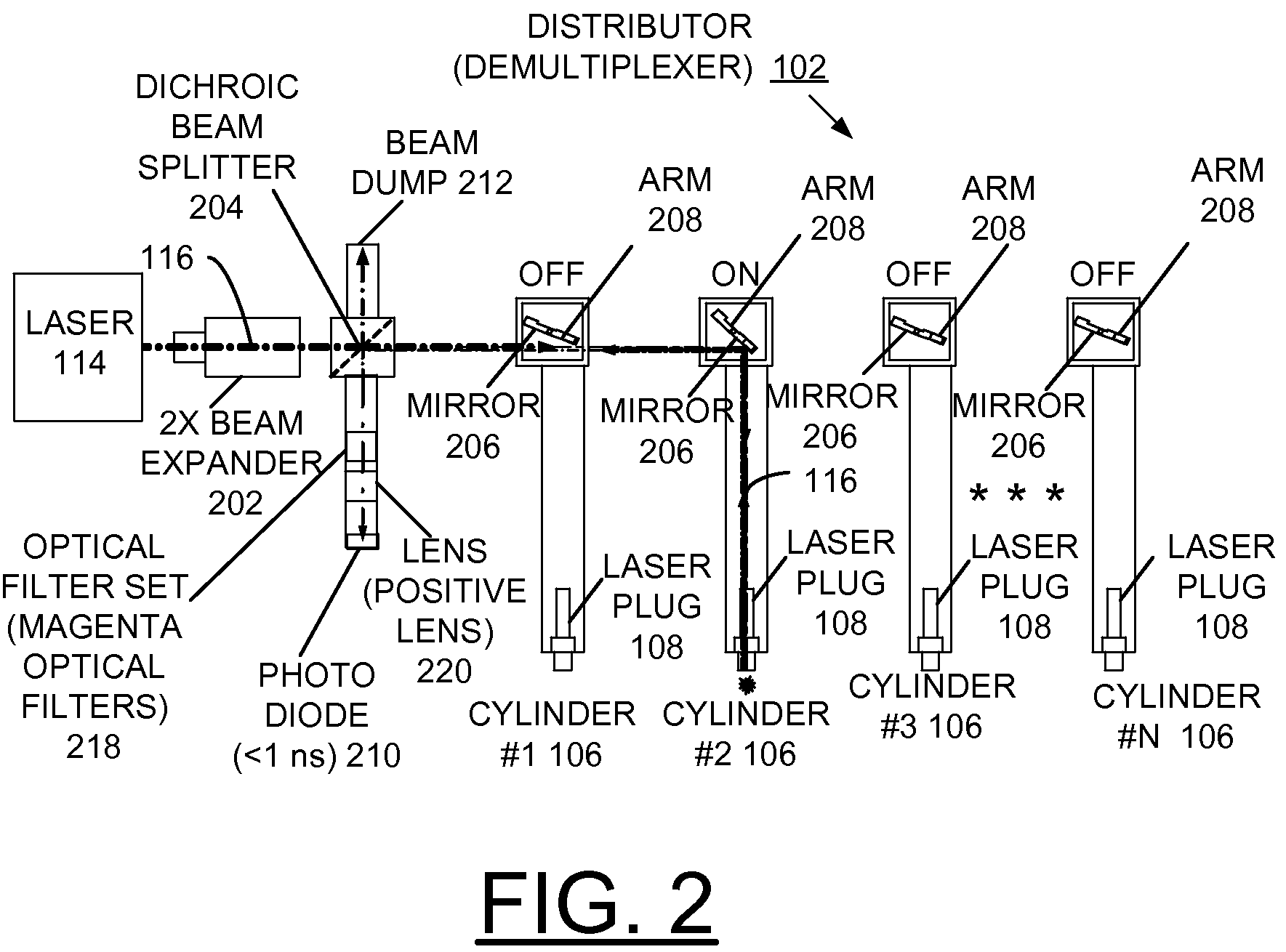
[0025]Having reference now to the drawings, FIG. 1 illustrates an exemplary laser pulse distribution system generally designated by reference character 100 in accordance with the preferred embodiment. Laser pulse distribution system 100 includes a distributor 102 coupled to a multi-cylinder engine 104. The distributor 102 implements a laser output pulse demultiplexing method in accordance with the preferred embodiment.

[0026]In accordance with features of the invention, the distributor 102 distributes high-power laser pulses to create sparks in each of a plurality of individual cylinders 106 of the multi-cylinder engine 104. The distributor distributes individual laser output pulses to each of a plurality of laser plugs 108 for providing spark generation. A respective laser plug 108 of the plurality of laser plugs 108 is installed in a respective individual cylinder 106.

[0027]An electronic control unit (ECU) 110 is provided to obtain the correct spark timing with crankshaft orientati...


PUM


Abstract

A method and system to distribute high-power laser pulses to create sparks in individual cylinders of a multi-cylinder engine are provided. A laser provides laser output pulses. A distributor includes a linear array of mirrors with a respective mirror associated with one of the laser plugs. Each mirror is operatively controlled to move into a laser beam path to direct individual laser output pulses the associated laser plug for providing spark generation. The system enables correct cylinder firing order for predefined multi-cylinder firing sequences and allows for individual cylinder timing variation.

Description

CONTRACTUAL ORIGIN OF THE INVENTION[0001]The United States Government has rights in this invention pursuant to Contract No. W-31-109-ENG-38 between the United States Government and The University of Chicago and / or pursuant to Contract No. DE-AC02-06CH11357 between the United States Government and UChicago Argonne, LLC representing Argonne National Laboratory.FIELD OF THE INVENTION[0002]The present invention relates to a method and distribution system for high power lasers, and more particularly to a method and system to distribute high-power laser pulses to create sparks in individual cylinders of a multi-cylinder engine, such as a stationary natural gas engine.DESCRIPTION OF THE RELATED ART[0003]Stationary natural gas multi-cylinder engines are currently used for power generation and pumping applications. Natural gas engines are preferred over diesel engines because they are environmentally cleaner than diesel, and in certain locations, such as natural gas fields, natural gas is mo...

Claims


Application Information

Patent Timeline
Patent Type & Authority Patents(United States)
IPC IPC(8): F02B1/02
CPCF02P5/1512F02P23/04Y02T10/46Y02T10/40
Inventor BIHARI, BIPINGUPTA, SREENATH BORRASEKAR, RAMANUJAM RAJ
Owner UCHICAG ARGONNE LLC
Why Eureka
Try Eureka