Ball joint

a ball joint and ball head technology, applied in the direction of shafts, bearings, stents, etc., can solve the problems of affecting the performance of the ball joint, the ball head can be played in the housing, and the play is basically undesirable, so as to achieve the effect of favourable cos

Active Publication Date: 2010-08-31
THK RHYTHM AUTOMOTIVE GMBH
View PDF24 Cites 4 Cited by
  • Summary
  • Abstract
  • Description
  • Claims
  • Application Information

AI Technical Summary

Benefits of technology

[0010]A feature of the invention consists in further developing a ball joint of the type initially mentioned to the effect that it can be produced at a favourable cost and nevertheless a play is prevented from occurring inside the housing.

Problems solved by technology

Generally in ball joints and particularly in axial ball joints, the problem arises that with increasing wear of the bearing shell, a play of the ball head in the housing can occur.
This play is basically undesirable.
It is clearly undesirable if a worn ball joint has play.
On the one hand, the play leads to noises when the ball head is moved from one side of the bearing shell to the other when the load direction is reversed.
On the other hand, the play leads to increased stresses of the ball joint and of the components coupled therewith when the load direction is reversed.
However, a disadvantage in the known ball joint is that an additional component is present in the form of the rubber ring, which must be produced, kept in readiness and installed.
This leads to increased costs.

Method used


Image

  • Ball joint
  • Ball joint
  • Ball joint

Examples


Embodiment Construction

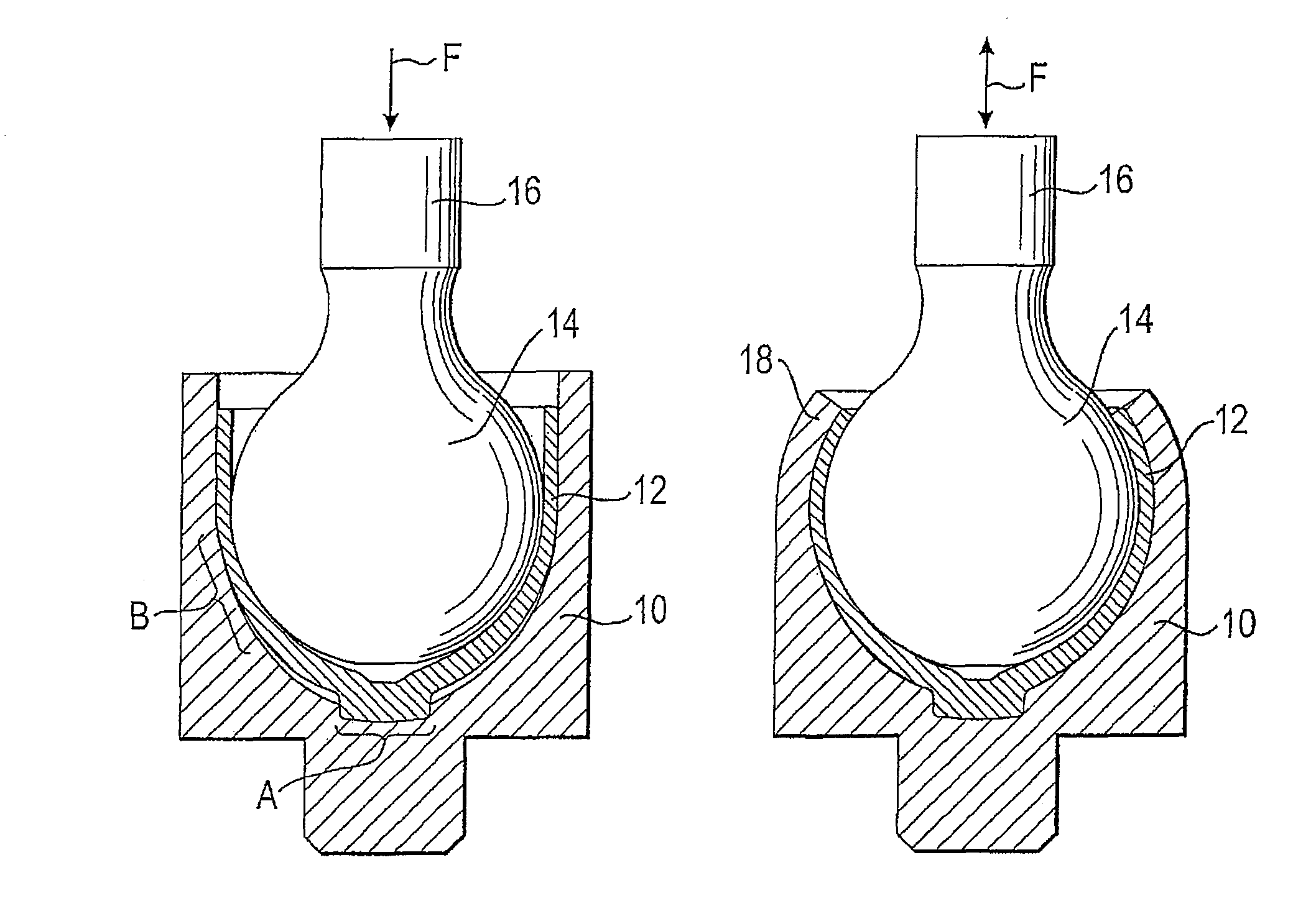
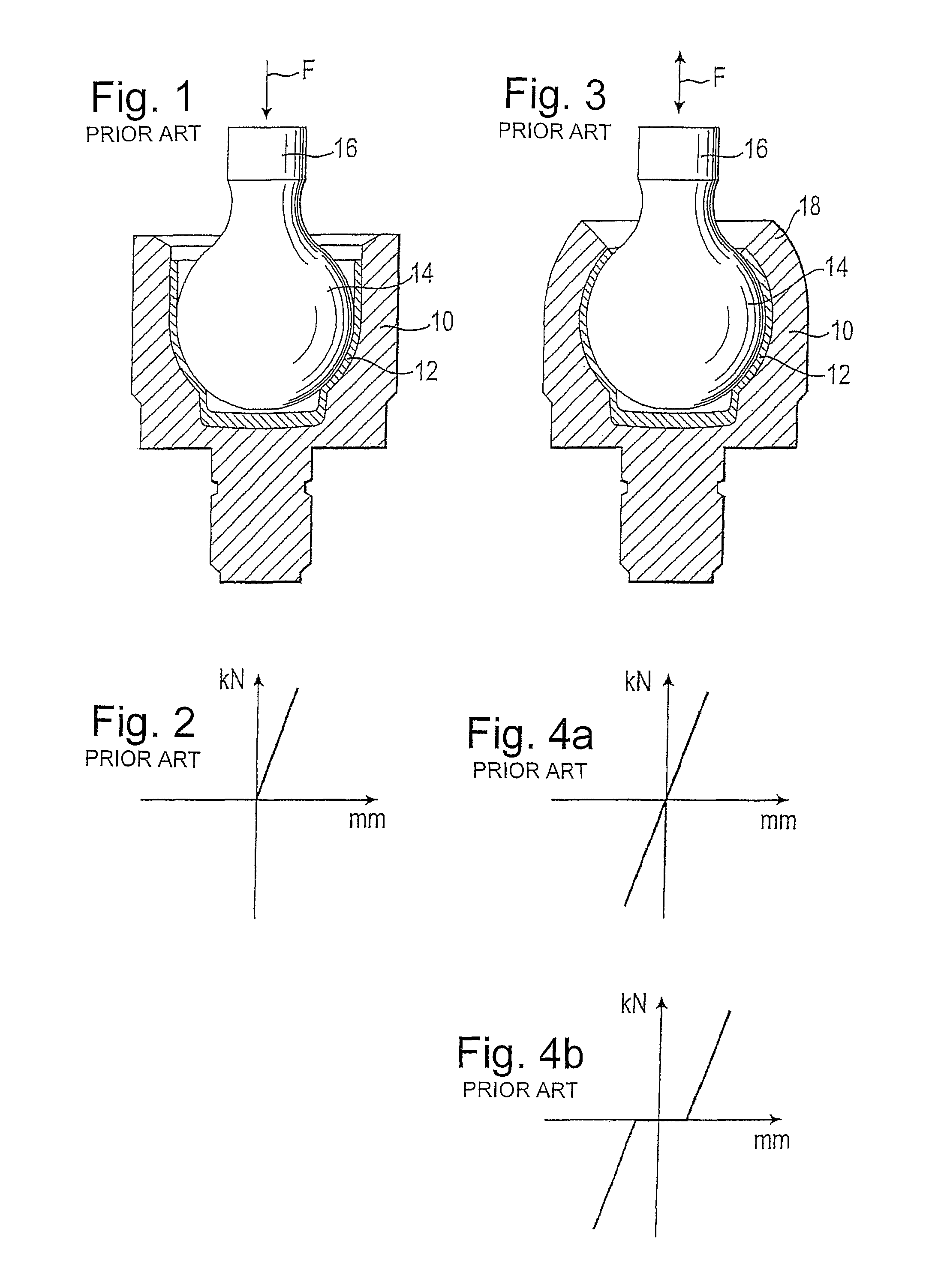
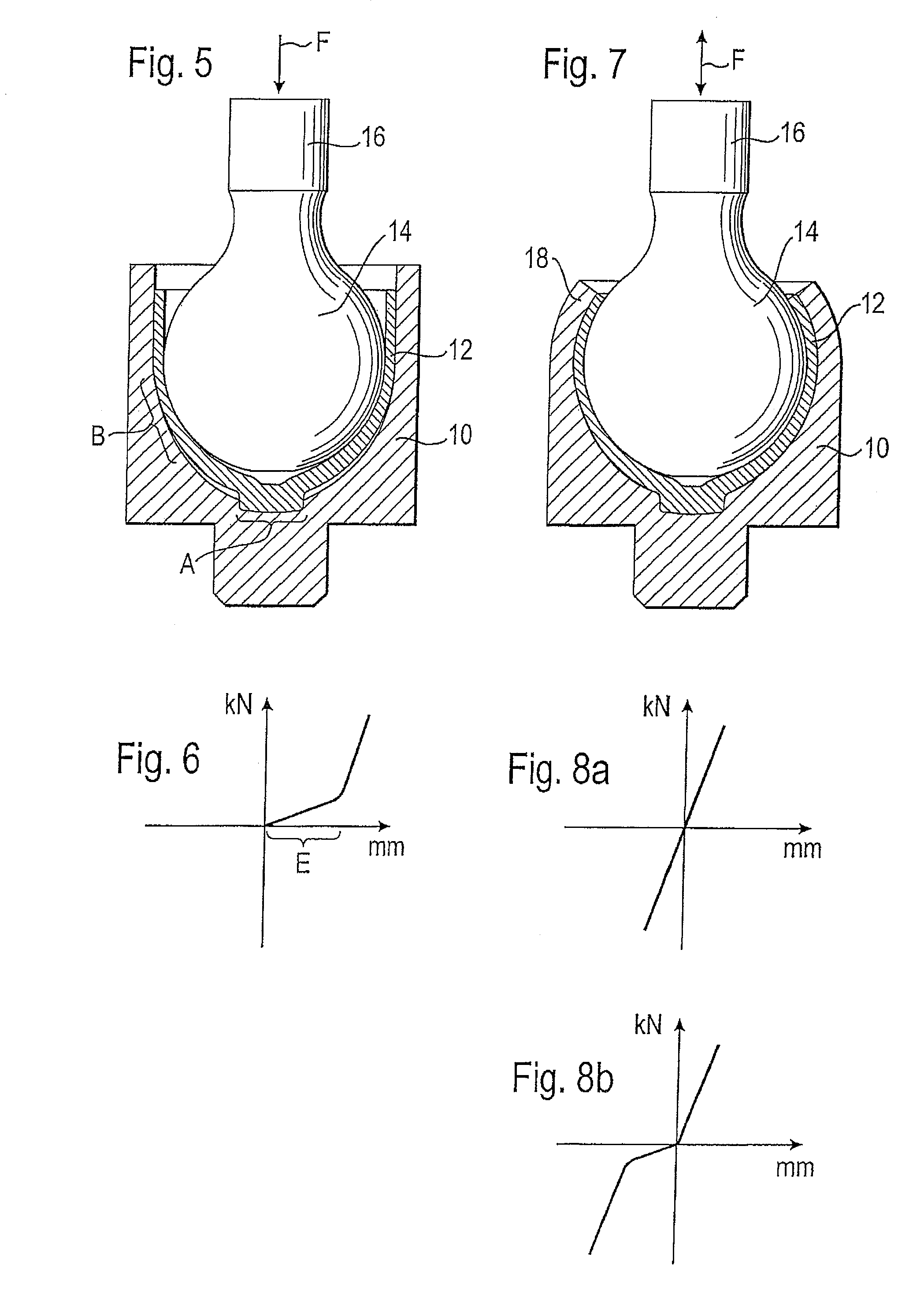
[0022]In FIG. 5 a ball joint can be seen, which in the same manner as the ball joint known from FIG. 1 has a housing 10 in which a bearing shell 12 is arranged, which in turn holds a ball head 14 of a ball pin 16. In contrast to the ball joint of FIG. 1, the bearing shell 12 here is constructed with an internal space the dimensions of which, expressed in general terms, are smaller than the dimensions of the ball head 14. In particular, in an encircling region B which lies slightly below the equator of the ball head 14, the bearing shell has a radius of curvature which is smaller than the radius of the ball head. This leads to the ball head 14 not being able to be fully inserted into the bearing shell 12 and the housing 10. It can be seen that an encircling free space remains both between the ball head and the bearing shell and also between the bearing shell and the housing.

[0023]If the ball head 14 is stressed in this state in the direction of the arrow F, the characteristic of load...


PUM


Abstract

A ball joint, particularly an axial joint, having a housing, a bearing shell which is arranged in the housing, and a ball pin with a ball head which is arranged in the bearing shell, is characterized in that the bearing shell is bent open elastically by the ball head so that the restoring force resulting from its deformation applies a prestress onto the ball head which attempts to press the latter out of the housing.

Description

CROSS-REFERENCE TO RELATED APPLICATIONS[0001]This application is a National Stage of International Application No. PCT / EP2007 / 001282 filed Feb. 14, 2007, the disclosures of which are incorporated herein by reference in entirety, and which claimed priority to German Patent Application No. 10 2006 008 250.8 filed Feb. 22, 2006, the disclosures of which are incorporated herein by reference in entirety.BACKGROUND OF THE INVENTION[0002]The invention relates to a ball joint, particularly an axial joint, having a housing, a bearing shell which is arranged in the housing, and a ball pin with a ball head which is arranged in the bearing shell.[0003]Generally in ball joints and particularly in axial ball joints, the problem arises that with increasing wear of the bearing shell, a play of the ball head in the housing can occur. This play is basically undesirable.[0004]An axial ball joint according to the prior art is shown in FIGS. 1 and 3. In FIG. 1, the axial ball joint is shown in an instal...

Claims


Application Information

Patent Timeline
Patent Type & Authority Patents(United States)
IPC IPC(8): F16C11/00A61F2/958
CPCF16C11/0638F16C11/0647Y10T403/32713Y10T403/32721Y10T403/32737
Inventor SCHAUMANN, LOTHAR
Owner THK RHYTHM AUTOMOTIVE GMBH
Why Eureka
Try Eureka