Winding structure of rotating electric machine

a technology of rotating electric machines and winding rods, which is applied in the direction of windings, dynamo-electric components, synchronous machines, etc., can solve the problems of increasing vibration and noise of rotating electric machines, deteriorating workability, and increasing siz

Active Publication Date: 2010-11-16
TOYOTA JIDOSHA KK
View PDF33 Cites 2 Cited by
  • Summary
  • Abstract
  • Description
  • Claims
  • Application Information

AI Technical Summary

Benefits of technology

[0010]In the above-described structure, one set of the series-connected coils and the other set of the series-connected coils that are spaced apart from each other in the circumferential direction of the core body are arranged opposite to each other in the radial direction of the core body. Thus, even in the case where the rotor and stator are disposed eccentrically with respect to each other, electromagnetic balance is kept and generation of cyclic current in the parallel circuit is suppressed. Further, since the series-connected coils are wound oppositely in direction by turns in the order in which the coils are connected, the coils can be wound while coil twist is alleviated. Accordingly, the series-connected coils can successively be wound easily.
[0012]In the winding structure of the distributed-winding type, coils adjacent to each other in the circumferential direction of the core body are wound in respective directions opposite to each other. Thus, even in the case where the first and second coil groups each include a plurality of coils adjacent to each other in the circumferential direction of the core boy, these coils can be wound oppositely in direction by turns in the order in which these coils are connected in series. Accordingly, the series-connected coils can successively be wound easily. Further, by allowing some of the series-connected coils to be arranged adjacently, the wire connecting the coils can be shortened to downsize the rotating electric machine.

Problems solved by technology

Here, in a winding structure in which series-connected coils are connected in parallel with other series-connected coils, imbalance in electromotive force due to the eccentricity could generate cyclic current in the parallel circuit to accordingly cause increases of vibrations and noise of the rotating electric machine while it is driven.
However, as disclosed in Japanese Patent Laying-Open No. 2000-217290, in the case where parallel circuits are formed for each coil, the larger number of points of connection leads to deterioration in workability and increase in size.

Method used


Image

  • Winding structure of rotating electric machine
  • Winding structure of rotating electric machine
  • Winding structure of rotating electric machine

Examples


Embodiment Construction

[0026]In the following, a description is given of an embodiment of a winding structure of a rotating electric machine according to the present invention. It is noted that like or corresponding components are denoted by like reference characters and a description thereof may not be repeated depending on the case.

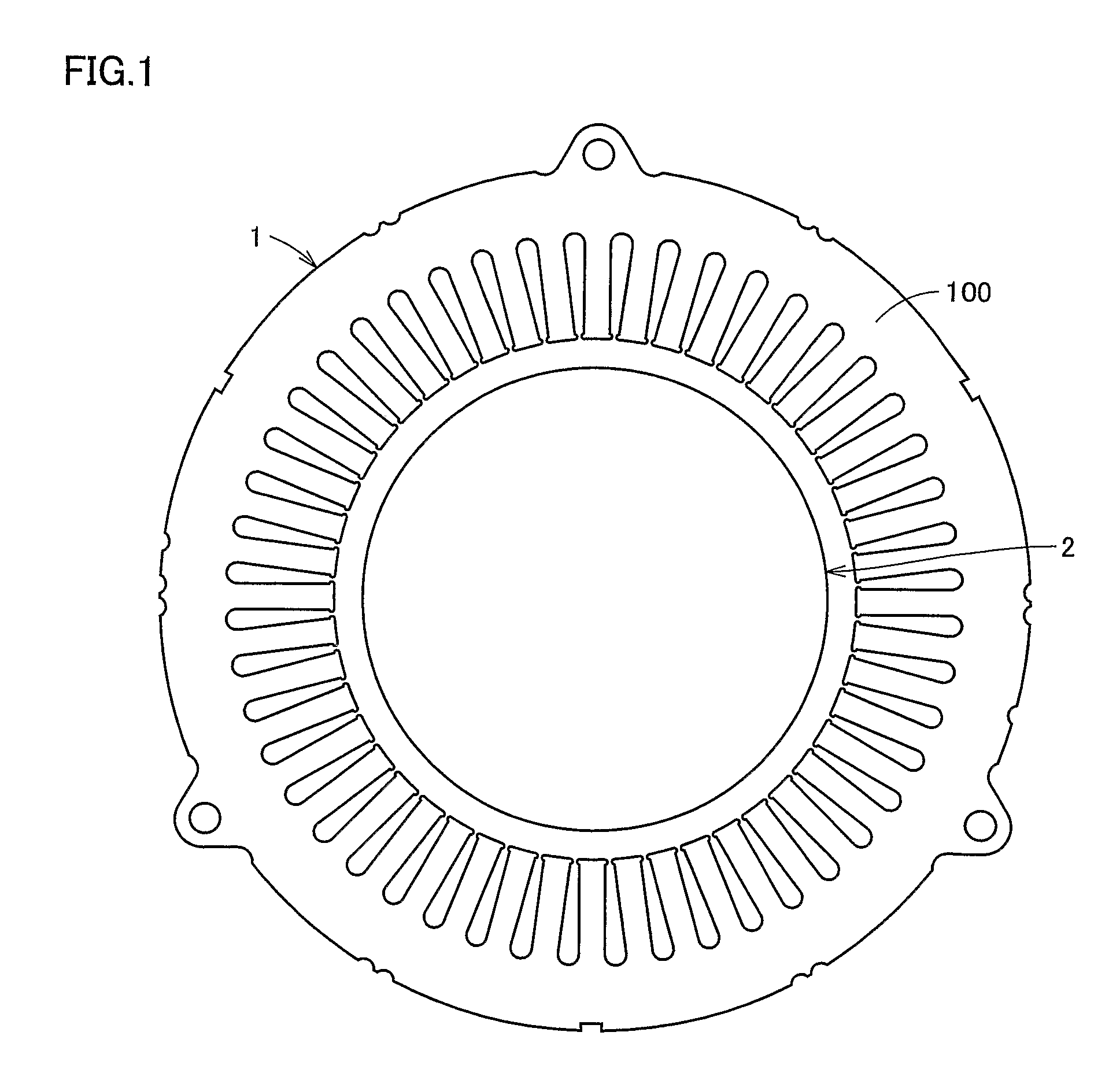
[0027]FIG. 1 is an axial cross-sectional view showing a rotating electric machine having a winding structure according to an embodiment of the present invention. Referring to FIG. 1, the rotating electric machine includes a stator 1 and a rotor 2. Stator 1 includes a stator core 100 corresponding to “core body” and a stator winding (not shown in FIG. 1) wound around stator core 100.

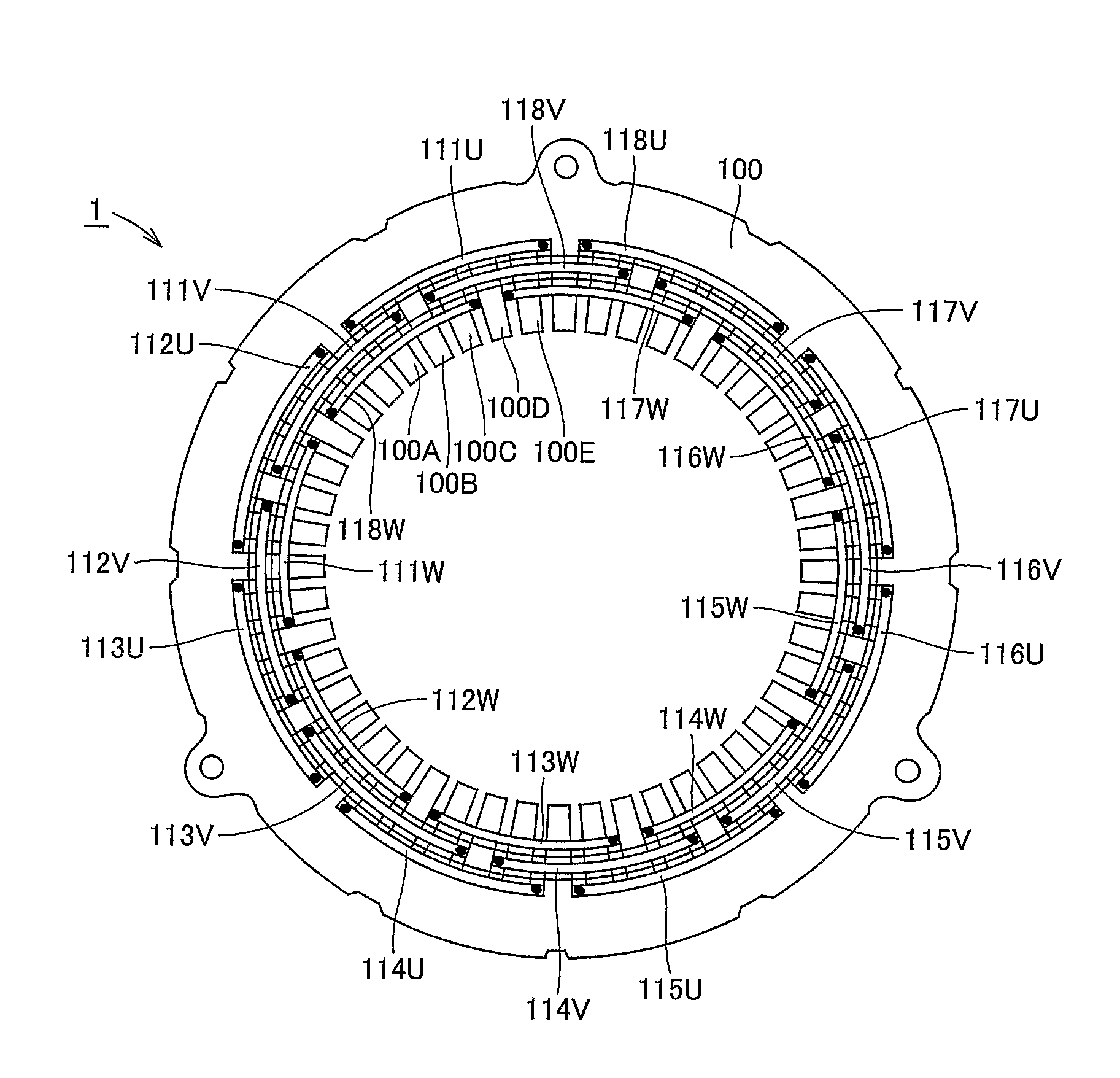
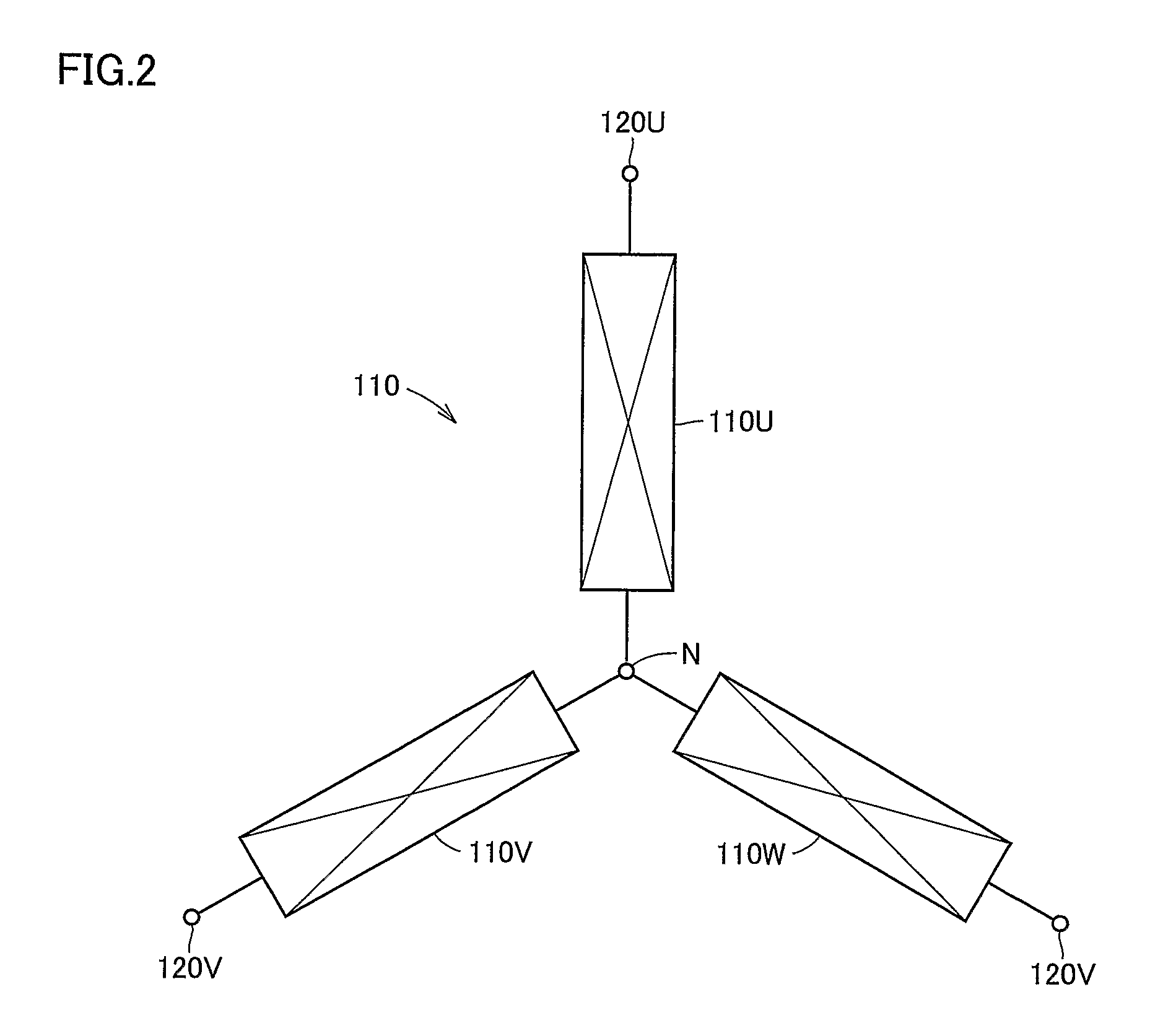
[0028]FIG. 2 shows a stator winding structure of the rotating electric machine shown in FIG. 1. Referring to FIG. 2, a stator winding 110 corresponding to “winding portion” includes a U phase coil 110U, a V phase coil 110V and a W phase coil 110W. Respective one ends of phase coils 110U, 110V and 1...


PUM


Abstract

In a stator winding, series coils are connected in parallel. One series coil includes series-connected U phase coils that are wound oppositely in direction by turns in the order in which the coils are series-connected and that are arranged in the manner that one and the other coil sets of the U phase coils are separated in the circumferential direction of a stator core and are opposite to each other in the radial direction thereof. The other series coil includes series-connected U phase coils that are wound oppositely in direction by turns in the order in which the coils are series-connected and that are arranged in the manner that one and the other coil sets of the U phase coils are separated in the circumferential direction of the stator core and are opposite to each other in the radial direction thereof.

Description

TECHNICAL FIELD[0001]The present invention relates to a winding structure of a rotating electric machine. In particular, the invention relates to a winding structure of a rotating electric machine having a core body and a winding portion.BACKGROUND ART[0002]Conventional winding structures of a rotating electric machine are for example disclosed in Japanese Patent Laying-Open Nos. 2000-217290 and 10-313557.[0003]Japanese Patent Laying-Open No. 2000-217290 discloses an electric motor in which windings of each phase are connected in the manner that windings opposite to each other in the radial direction are connected in parallel and a set of thus parallel-connected windings is connected in series with another set of parallel-connected windings.[0004]Japanese Patent Laying-Open No. 10-313557 discloses a rotating electric machine for which the number of turns of windings opposite to each other is adjusted so as to adjust unbalanced magnetic pull.[0005]In some cases, a rotor and a stator ...

Claims


Application Information

Patent Timeline
Patent Type & Authority Patents(United States)
IPC IPC(8): H02K1/00H02K3/00H02K19/26H02K23/02H02K21/00
CPCH02K3/28H02K3/12
Inventor HATTORI, HIROYUKI
Owner TOYOTA JIDOSHA KK
Why Eureka
Try Eureka