Card connector

a card connector and connector technology, applied in the direction of coupling device connection, engagement/disengagement of coupling parts, instruments, etc., can solve the problem of limiting the reduction of the overall achieve reliably electric contact, and reduce the height of the card connector

Active Publication Date: 2011-01-11
YAMAICHI ELECTRONICS +1
View PDF43 Cites 17 Cited by
  • Summary
  • Abstract
  • Description
  • Claims
  • Application Information

AI Technical Summary

Benefits of technology

[0016]The present invention includes a lock bracket and a actuator to allow two types of cards, large and small cards, to be prevented from being incorrectly inserted. Furthermore, a partition member moves upward and downward to allow the two types of cards, the large and small cards, to be reliably sorted. Additionally, the height of the card connector can be reduced. Moreover, the present invention allows cards to be inserted into the card connector both in a normal state and in a reverse state. This allows the contacts to be significantly displaced so as to reliably achieve electric contact, and enables a reduction in the height of the card connector. Furthermore, the present invention utilizes the rotation of the actuator to move the partition member. This enables a reduction in the number of components required, and allows the configuration of the card sorting mechanism to be simplified. Moreover, the present invention uses, pushup springs to bias the partition member upward and provides the vertical guide piece and the regulation pieces. This enables the partition member to be reliably moved upward and downward and allows the electric contact between each of the large and small cards and the corresponding contacts to be ensured.

Problems solved by technology

Furthermore, the relationship between the partition plate and the contacts arranged above and below the partition plate contributes to limiting reduction of the overall height of the card connector.

Method used


Image

  • Card connector
  • Card connector
  • Card connector

Examples


Embodiment Construction

[0040]A preferred embodiment of the present invention will be described below with reference to FIG. 1 to FIG. 14.

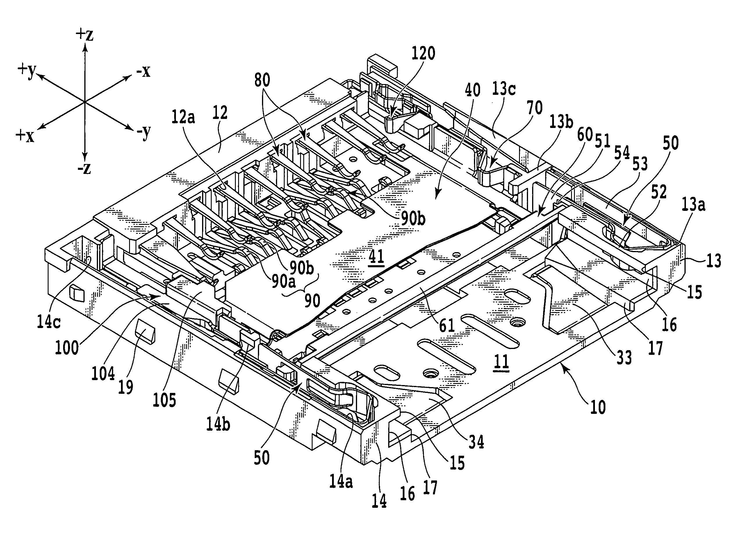
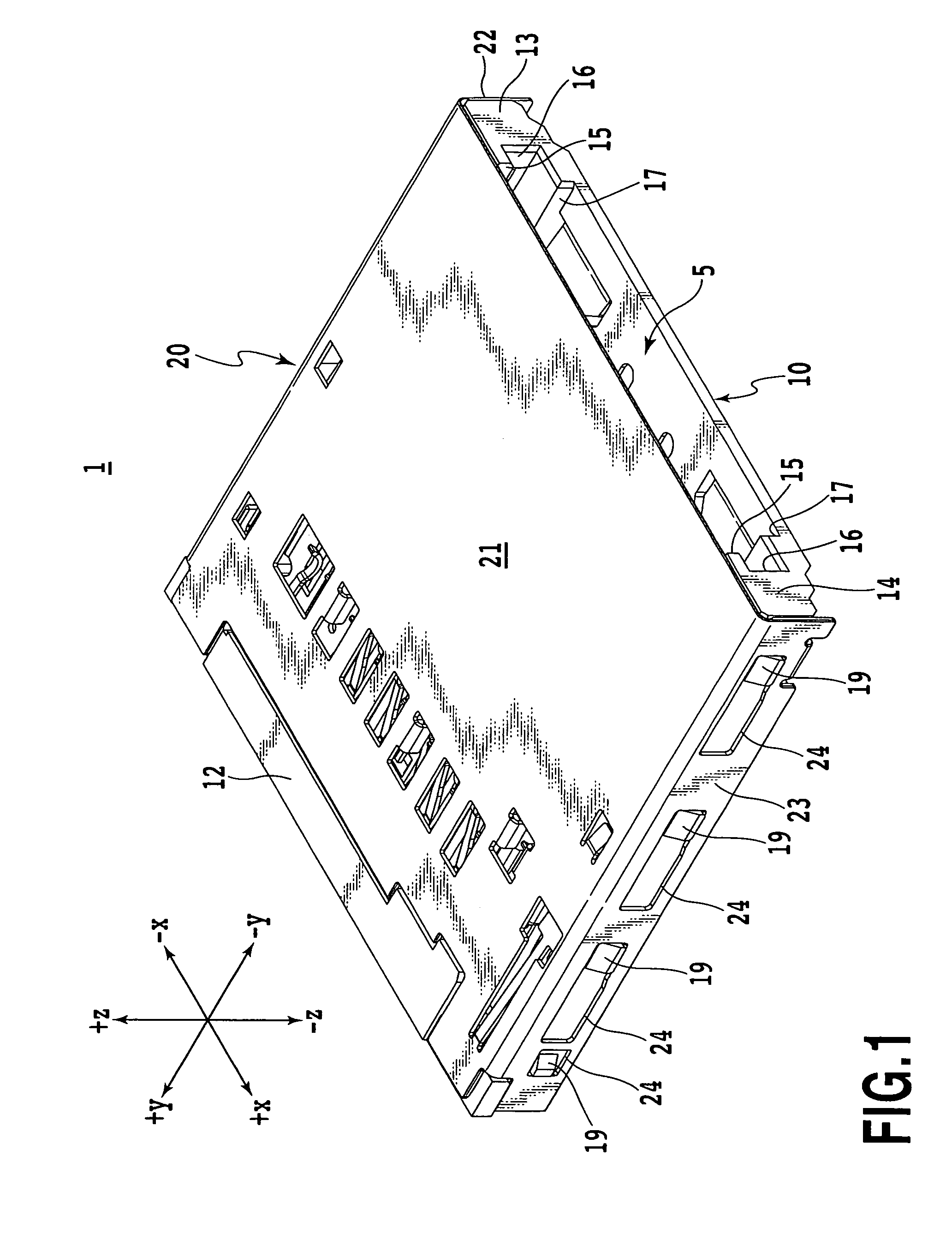
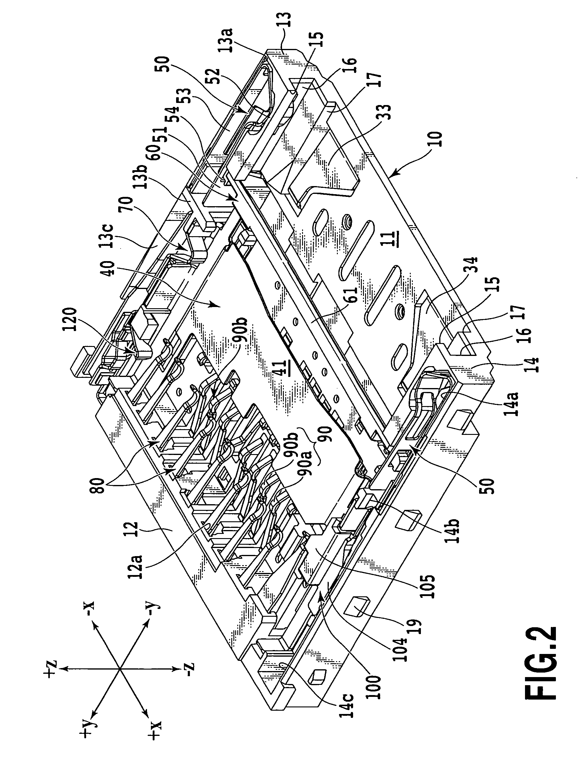
[0041]First, the configuration of a card connector will be described. FIG. 1 is a perspective view of the card connector according to the present invention. FIG. 2 is a perspective view of the card connector from which a cover member has been removed. FIG. 3A is a top view of the card connector shown in FIG. 1. FIG. 3B is a sectional view taken along line IIIB-IIIB in FIG. 3A. FIG. 4 is a top view of the card connector. FIG. 5A is a perspective view of a partition plate used for the card connector. FIG. 5B is a top view of the partition plate shown in FIG. 5A. FIG. 14A is a top view of an insert embedded in a base member. FIG. 14B is a side view of the insert shown in FIG. 14A.

[0042]In the description below, the terms “left” and “right” refer to the +x direction and −x direction, respectively, in the coordinate system shown in FIGS. 1 and 2. The terms “front” and “rear” ...


PUM


Abstract

A card insertion slot in the card connector through which two types of cards, large and small cards, can be selectively installed in a card accommodation space include first and second guideways in corresponding to the sizes of the cards. The card connector includes first and second contacts, a lock bracket configured to detect the width of the large card, an actuator configured to be rotatable, and a partition member including a partition plate configured to be movable. When the large card is inserted into the card connector, the lock bracket is moved from the first position to the second position. When the large card is further fed into the card connector, the actuator is rotated from the first position to the second position, and the partition plate is moved from the first position to the second position.

Description

CROSS-REFERENCE TO RELATED APPLICATIONS[0001]This application claims the benefit of Japanese Patent Application No. 2009-158094, filed Jul. 2, 2009, which is hereby incorporated by reference herein in its entirety.BACKGROUND OF THE INVENTION[0002]1. Field of the Invention[0003]The present invention relates to a card connector in which cards of different sizes can be installed through one card insertion slot, and more specifically, to a card connector in which an actuator configured to sort cards in accordance with the sizes of the cards enables movement of a movable plate configured to guide each card upward and downward.[0004]2. Description of the Related Art[0005]In connection with electronic apparatuses and information terminal apparatuses, card connectors are known in which a card with a built-in integrated circuit (hereinafter simply referred to as an “IC card”) used as a CPU or a memory is installed in order to enhance the functions of the electronic apparatus. On the other ha...

Claims


Application Information

Patent Timeline
Patent Type & Authority Patents(United States)
IPC IPC(8): H01R24/00
CPCG06K7/0043G06K7/0047H01R27/00
Inventor SATO, SHIGERUKOYASU, MASATOTAKAI, YOSUKEOSHIMA, MASAAKI
Owner YAMAICHI ELECTRONICS
Why Eureka
Try Eureka