Vortex waste separator apparatus

a technology of separator and jet, which is applied in the direction of liquid degasification, separation process, water/sewage treatment by degassing, etc., can solve the problems of reducing fuel efficiency, releasing visible undesirable particulate human waste into the atmosphere, and accumulating ice on the aircraft fuselag

Active Publication Date: 2011-08-16
BE AEROSPACE INCORPORATED
View PDF28 Cites 38 Cited by
  • Summary
  • Abstract
  • Description
  • Claims
  • Application Information

AI Technical Summary

Benefits of technology

[0012]Finally, a helix isolator may be provided in the area outside of the filter unit to help prevent cross-contamination of the waste stream falling to the waste tank for collection and later disposal and the lighter substantially waste-free airstream advancing into the filter unit. The helix separator includes a hollow central member attached outside of the filter unit with a pair of helical vanes extending out to the inner surface of the separator and baffles on the vanes and at the entrance to the central member to capture and direct the liquid and solid waste downwardly while blocking its upward movement.
[0016]Finally, an exhaust member may be generally centered in the conical chamber. The exhaust member has an annular shelf positioned above the chamber and the top closure of the cones. It also has a central tubular portion projecting downwardly into the chamber defining an exit conduit leading from the chamber to the top of the cylindrical housing of the separator. Thus, the airstream exiting the chamber will pass through the tubular portion before being removed from the top of the housing via the exhaust port. Finally, a demister filter may be disposed across the top opening of the tubular portion to help remove any remaining moisture in the exiting airstream.

Problems solved by technology

As to sanitary concerns, it is obviously undesirable to release particulate human waste into the atmosphere, either when the aircraft is airborne or when it is on the ground.
Additionally, there is a danger that if a substantial amount of water escapes the aircraft from such a vacuum driven aircraft waste collection system, it may build up on the aircraft fuselage to form ice.
Conventional aircraft waste material separation systems are large and so require excessive space in the aircraft while contributing unnecessarily to the aircraft weight, reducing its fuel efficiency.
Also, conventional waste material separation systems require frequent servicing, which is often difficult and time-consuming to perform because of inconvenient access to the separator apparatus.

Method used


Image

  • Vortex waste separator apparatus
  • Vortex waste separator apparatus
  • Vortex waste separator apparatus

Examples


Embodiment Construction

[0028]The embodiment of the invention described below is not intended to be exhaustive or to limit the invention to the precise structure and operation disclosed. Rather, the embodiment described in detail below has been chosen and described to explain the principles of the invention and its application, operation and use in order to best enable others skilled in the art to follow its teachings.

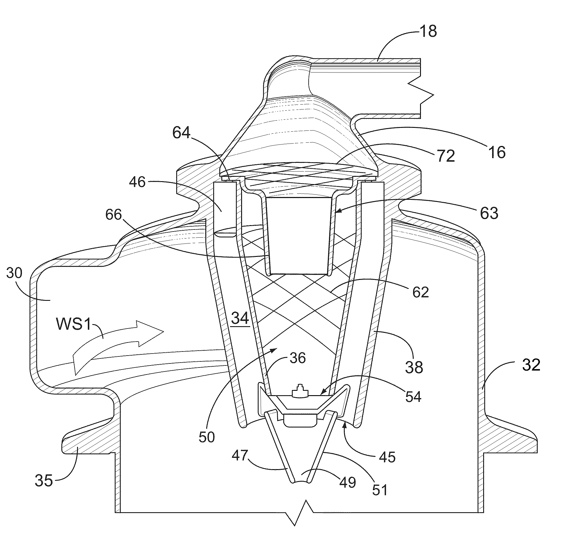
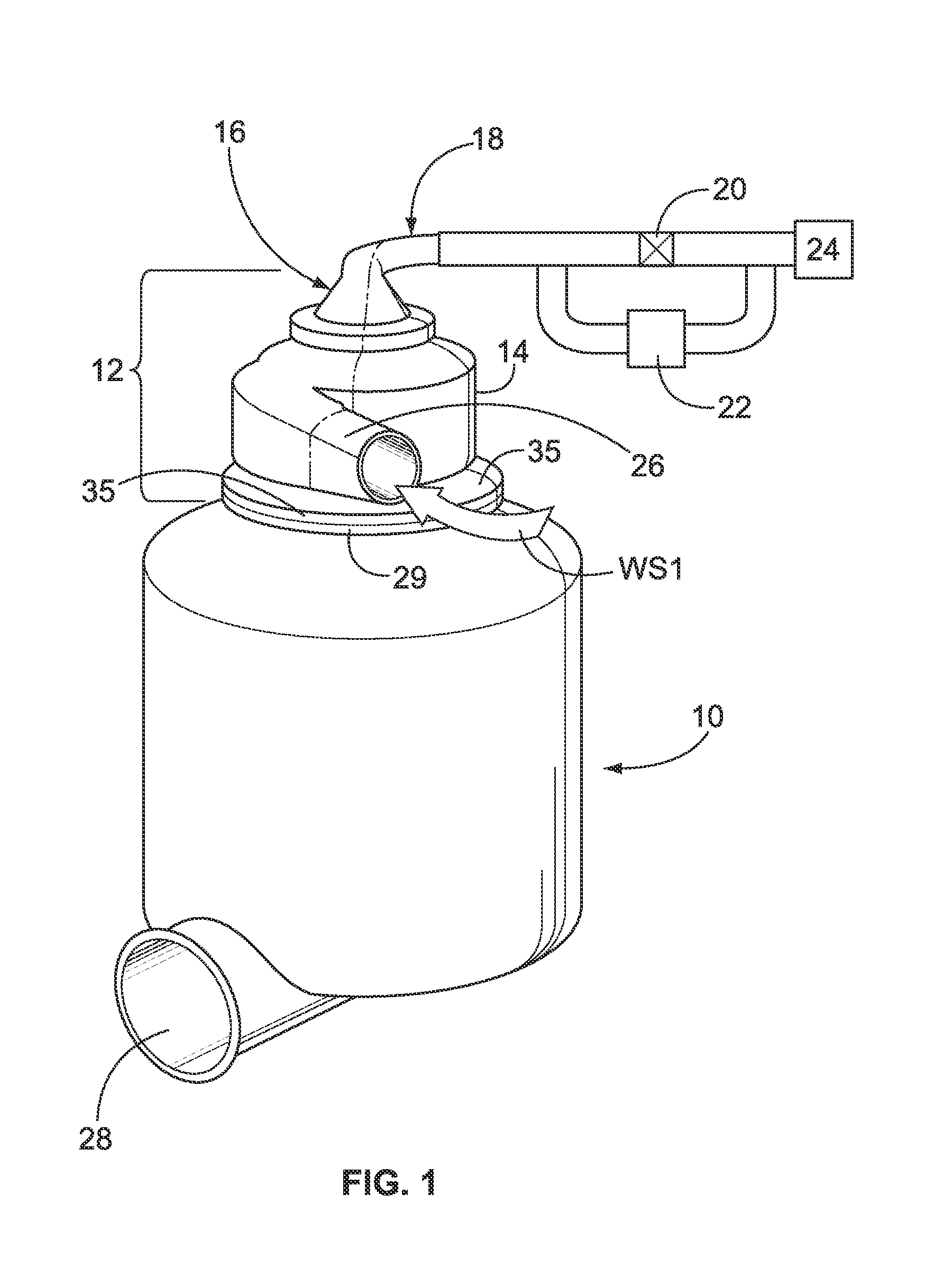
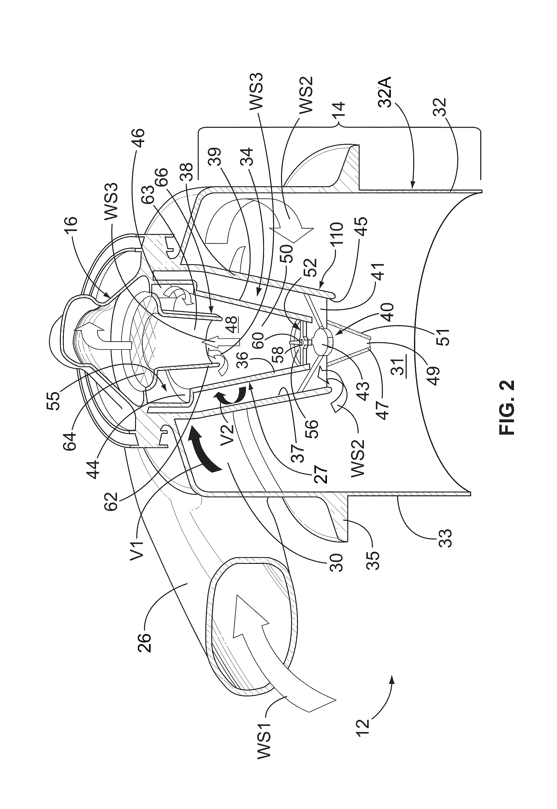
[0029]Turning now to FIG. 1, the exterior of a waste tank 10 having a vortex waste separator 12 in accordance with the invention is illustrated. The vortex separator 12 includes a housing 14 that is preferably cylindrical as shown and an exhaust cap 16 with an exhaust tube 18 atop the housing. The exhaust cap may be removably clamped to the top of the cylindrical housing to permit access to the interior of the separator when desired and to permit removal and replacement of a filter unit cartridge in one preferred embodiment of the invention. Exhaust tube 18 will be connected as shown diagramm...


PUM

PropertyMeasurementUnit
altitudesaaaaaaaaaa
altitudesaaaaaaaaaa
suctionaaaaaaaaaa

Abstract

A vortex separator for drawing a substantially moisture-free airstream from a waste stream having an annular channel defining a first vortex flow path for separating liquid and solid waste from this waste stream and preferably a filter unit with an inverted conical cavity between nested inverted cones defining a second vortex flow path that is isolated from the first vortex flow path for separating additional liquid and solid waste from the waste stream before it exits the vortex separator. In preferred embodiments, the separator includes a removable filter unit cartridge positioned within the outer cone and a helix isolator to respectively make use of the separator more convenient to use and more efficient.

Description

CROSS-REFERENCE TO RELATED PATENT APPLICATION[0001]This patent application is a continuation-in-part of copending U.S. patent application Ser. No. 12 / 245,541, filed Oct. 3, 2008.FIELD OF THE INVENTION[0002]This invention pertains to systems for separating aircraft waste and, more particularly, to a vortex apparatus for removing solid and liquid waste from a waste stream from aircraft toilets or other receptacles while withdrawing a substantially moisture-free airstream under suction.BACKGROUND OF THE INVENTION[0003]Various systems are available in the art that employ a vacuum to transport liquid and solid waste material from aircraft toilets or other receptacles to a waste tank for storage. The waste material that is transported includes solid human waste, urine, water, optionally cleansing and disinfecting chemicals, air, toilet paper, food, and often unexpected discarded items, all of which are drawn from the aircraft toilets or other receptacles to one or more waste tanks. The wa...

Claims


Application Information

Patent Timeline
Patent Type & Authority Patents(United States)
IPC IPC(8): C02F1/20
CPCB01D45/16B04C5/04B04C5/15B04C5/26B04C9/00B04C2009/004B64D11/02C02F1/38B04C2005/136B04C5/13
Inventor PONDELICK, MARK A.HARDWICK, CHRISTOPHERVAUGHAN, DEREKHOANG, THAOFUNK, MICHAEL
Owner BE AEROSPACE INCORPORATED
Why Eureka
Try Eureka