Injector for betatron

a betatron and injector technology, applied in the direction of discharge tubes/lamp details, single discharge path tubes, electrostatic control tubes, etc., can solve the problems of strict control, source radiation hazards, and most sources having a long half li

Inactive Publication Date: 2011-10-11
SCHLUMBERGER TECH CORP
View PDF30 Cites 2 Cited by
  • Summary
  • Abstract
  • Description
  • Claims
  • Application Information

AI Technical Summary

Benefits of technology

[0016]According to another embodiment of the invention, the invention has an electron acceleration portion of Betatron including a vacuum chamber having an interior wall spaced from an exterior wall and a top wall and a bottom wall with a main electron orbit located between the exterior wall and the interior wall and between the top wall and the bottom wall. The above-noted embodiment further includes an electron injector having an electron emitting cathode spaced from an anode, such that the electron injector can be structured and arranged adjacent one of the top wall and the bottom wall and shaped so as to not impede the main electron orbit. Further, at least one electron deflection plate can be disposed approximate an anode end of the anode and the main electron orbit.

Problems solved by technology

These sources pose a radiation hazard and require strict controls to prevent accidental exposure or intentional misuse.
In addition, most sources have a long half life and disposal is a significant issue.
With an internal injector, accurate control of the injection angle becomes more difficult and adjustments after sealing the vacuum chamber are difficult or impossible.

Method used


Image

  • Injector for betatron
  • Injector for betatron
  • Injector for betatron

Examples


Embodiment Construction

[0035]The particulars shown herein are by way of example and for purposes of illustrative discussion of the embodiments of the present invention only and are presented in the cause of providing what is believed to be the most useful and readily understood description of the principles and conceptual aspects of the present invention. In this regard, no attempt is made to show structural details of the present invention in more detail than is necessary for the fundamental understanding of the present invention, the description taken with the drawings making apparent to those skilled in the art how the several forms of the present invention may be embodied in practice. Further, like reference numbers and designations in the various drawings indicated like elements.

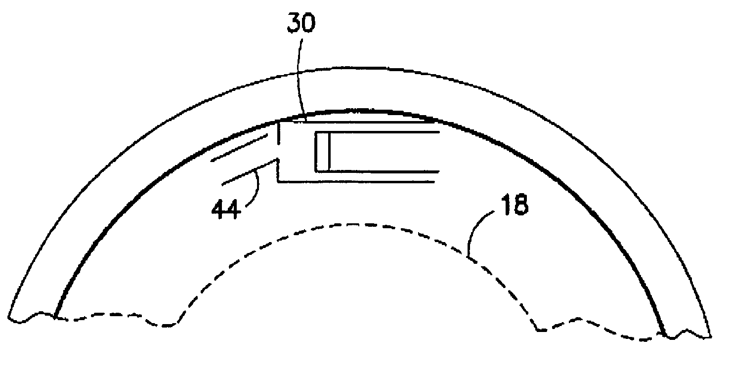
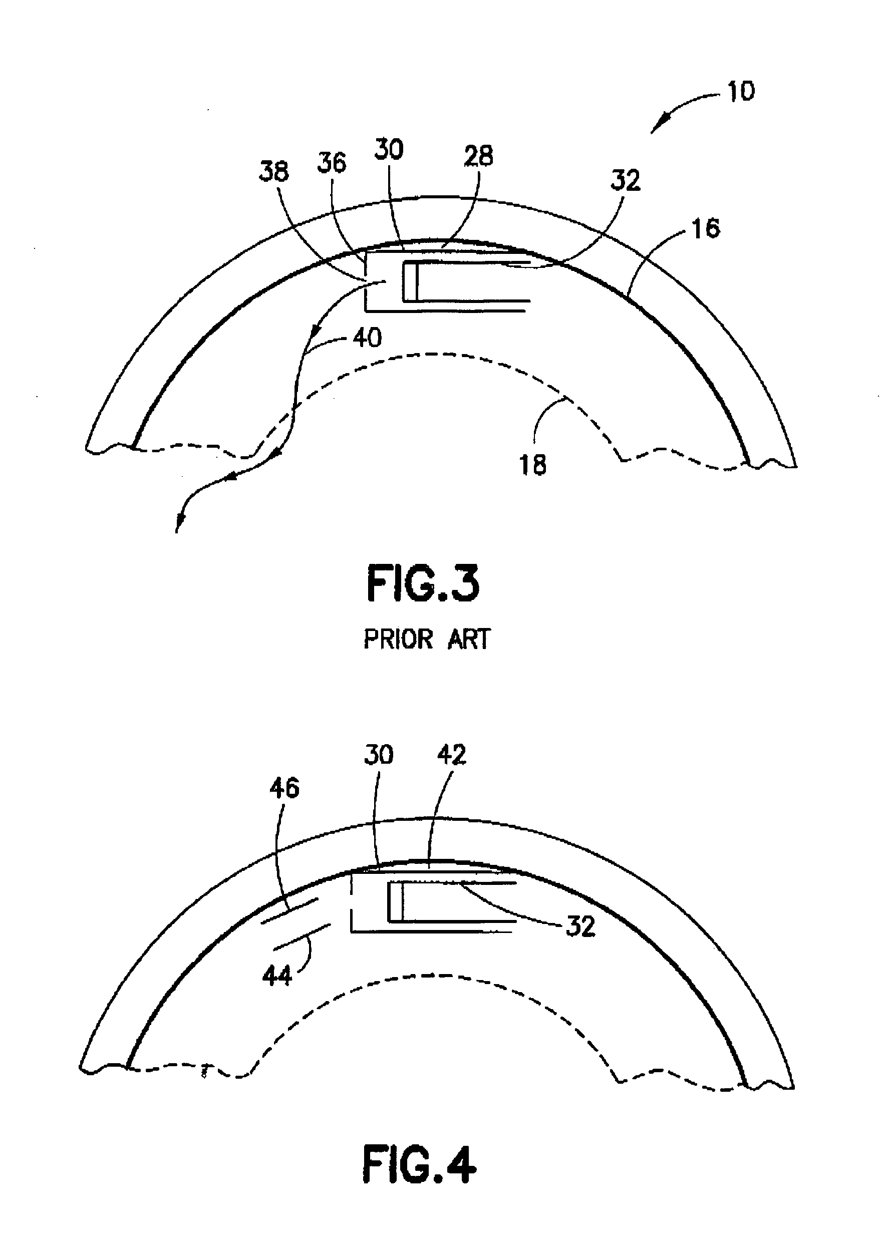
[0036]According to an embodiment of the invention, the invention can have an electron acceleration portion of a Betatron including a vacuum chamber with an interior wall spaced from an exterior wall with a main electron orbit...


PUM


Abstract

An electron acceleration portion of a Betatron having a vacuum chamber with an interior wall spaced from an exterior wall with a main electron orbit located approximate to the exterior wall and the interior wall. An electron injector has an anode structured and arranged adjacent a wall selected from the group consisting of the interior wall and the exterior wall that is shaped so as to not impede the main electron orbit. There is at least one electron deflection plate disposed approximate an anode end of the anode and the main electron orbit. There can be two electron deflection plates spaced apart that form a gap of a width effective to receive emitted electrons from the electron injector. Such that, there is a voltage potential between the two electron deflection plates that is effective to deflect emitted electrons towards the main electron orbit.

Description

BACKGROUND OF THE INVENTION[0001]1. Field of the Invention[0002]The invention is generally related to circular electron accelerators. More particularly, a combination of an internal electron injector and electrostatic deflection electrodes enhances the number of injected electrons that enter a main electron orbit of a Betatron and are accelerated to relativistic velocity.[0003]2. Background of the Invention[0004]Oil well bore hole logging is a process by which properties of earth strata as a function of depth in the bore hole are measured. A geologist reviewing the logging data can determine the depths at which oil containing formations are most likely located. Most present day well logging relies on gamma-rays obtained from chemical radiation sources to determine the bulk density of the formation surrounding a borehole. These sources pose a radiation hazard and require strict controls to prevent accidental exposure or intentional misuse. In addition, most sources have a long half l...

Claims


Application Information

Patent Timeline
Patent Type & Authority Patents(United States)
IPC IPC(8): H05H11/00
CPCH05H11/00
Inventor CHEN, FELIXSTOLLER, CHRISTIANPHILIP, OLIVIERPERKINS, LUKE T.
Owner SCHLUMBERGER TECH CORP
Why Eureka
Try Eureka