Check patentability & draft patents in minutes with Patsnap Eureka AI!

Apparatus and method of motion adaptive image processing

a technology of motion adaptive image and image processing, applied in the field of motion adaptive image processing, can solve the problems of all sampling aspects giving rise to alias effects, affecting the quality of images,

Inactive Publication Date: 2011-11-08
SONY UK LTD
View PDF19 Cites 1 Cited by
  • Summary
  • Abstract
  • Description
  • Claims
  • Application Information

AI Technical Summary

Benefits of technology

[0016]Advantageously, the above aspects allow an image to be processed with a conditional usage of the more sensitive motion detection method. Consequently, detailed motion detection can therefore still be applied around the edges of a region of motion to more accurately determine its extent, whilst at the same time mitigating the effects of motion noise in generally static regions. This serves to improve overall picture quality for example in an interlace to progressive scan conversion.

Problems solved by technology

A complication is the common use of interlaced video capture and processing.
All of these aspects of sampling can give rise to alias effects if an attempt is made to capture or process video material having spatial or temporal frequencies which are too high for the respective sampling rate.
However, if there is any significant inter-field motion, this approach may not work.
Interpolation will generally give a worse result than interleaving for non-moving portions, whereas interleaving and will generally give a worse result than interpolation for moving portions.
Notably, the presence of noise within the video signal can cause differences between successive fields that may be erroneously interpreted as motion, causing in turn different interpolation strategies to be used that give different output results in the progressive image, thereby exacerbating the noise.

Method used


Image

  • Apparatus and method of motion adaptive image processing
  • Apparatus and method of motion adaptive image processing
  • Apparatus and method of motion adaptive image processing

Examples


Embodiment Construction

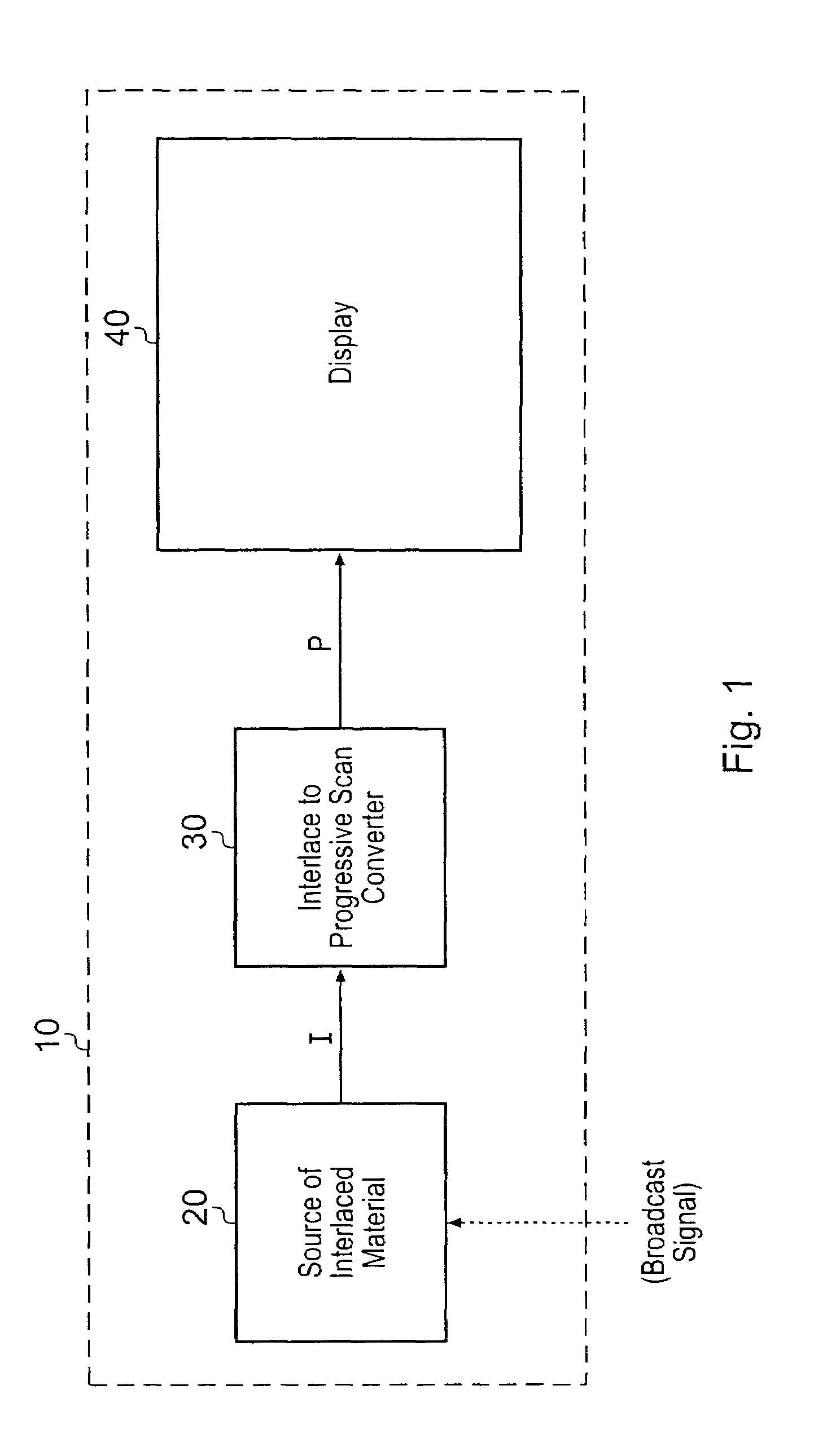
[0033]FIG. 1 schematically illustrates a flat screen display arrangement 10 comprising a source of interlaced video material 20, an interlace to progressive scan converter 30 and a display panel 40 such as a liquid crystal (LCD) or plasma display. This illustrates a typical use of interlace to progressive scan conversion, in that many broadcast signals are in the interlaced format whereas many flat panel displays operate most successfully in a progressive scan format. Accordingly, in FIG. 1, a broadcast signal received by the source of interlaced material 20 is used to generate an interlaced signal for display. This is passed to the interlace to progressive scan converter 30 to generate a progressive scan signal from the interlaced signal. It is the progressive scan signal which is passed to the display 40.

[0034]It will be appreciated that the source of interlaced material 20 need not be a broadcast receiver, but could be a video replay apparatus such as a DVD player, a network conn...


PUM


Abstract

An image processing apparatus includes a first motion detector, a second motion detector and a conversion selector. The first motion detector detects motion to a first level of spatial frequency sensitivity. The second motion detector detects motion to a second level of spatial frequency sensitivity greater than the first level of spatial frequency sensitivity to detect smaller amounts of motion than the first motion detector. The conversion selector selects contributions from at least one of a first conversion process and a second conversion process for a given point in an image dependant upon whether motion is detected by the first motion detector at the given point or not. The conversion selector operates independently of the second motion detector if a degree of motion within the image or a part thereof including the given point detected by the first motion detector does not exceed a threshold amount.

Description

BACKGROUND OF THE INVENTION[0001]1. Field of the Invention[0002]This invention relates to motion adaptive image processing.[0003]2. Description of the Prior Art[0004]Video image capture represents a spatial and temporal sampling process. An image is captured as a set of pixels arranged in rows or lines. Successive images are captured at spaced instants in time.[0005]A complication is the common use of interlaced video capture and processing. In an interlaced video signal, each image is handled as two sets or fields of alternate lines of pixels. For example, odd numbered lines might be included in one field, whereas even numbered lines could be included in the next field. An advantage of interlaced techniques is that they give an apparent doubling of the image rate, so reducing flicker effects, for no substantial increase in video signal bandwidth.[0006]All of these aspects of sampling can give rise to alias effects if an attempt is made to capture or process video material having sp...

Claims


Application Information

Patent Timeline
Patent Type & Authority Patents(United States)
IPC IPC(8): G06K9/00G06K9/36H04N5/44
CPCH04N7/012H04N7/014H04N5/144
Inventor BURNS, JAMES EDWARDSHARMAN, KARL JAMESSAUNDERS, NICHOLAS IANPORTER, ROBERT MARK STEFAN
Owner SONY UK LTD
Features
  • R&D
  • Intellectual Property
  • Life Sciences
  • Materials
  • Tech Scout
  • Unparalleled Data Quality
  • Higher Quality Content
  • 60% Fewer Hallucinations
Learn More