Liquid ejecting head unit and liquid ejecting apparatus

a liquid ejecting head and liquid ejecting technology, which is applied in the direction of printing, inking apparatus, etc., can solve the problems of increasing the size affecting the working efficiency of the attachment of the supply pipe and the circuit substrate, and affecting the working efficiency of the liquid ejecting head unit. , to achieve the effect of reducing the siz

Inactive Publication Date: 2011-11-15
SEIKO EPSON CORP
View PDF5 Cites 10 Cited by
  • Summary
  • Abstract
  • Description
  • Claims
  • Application Information

AI Technical Summary

Benefits of technology

[0008]Some aspects of the invention provide a liquid ejecting head unit and a liquid ejecting apparatus which attains reduction in size and facilitates assembling by simplifying piping and wiring.

Problems solved by technology

However, when the plurality of liquid ejecting heads are mounted on the platform, supply pipes connected to liquid passage ports of the plurality of liquid ejecting heads interfere with circuit substrates connected to connectors of the liquid ejecting heads.
Piping of the supply pipes and wiring of the circuit substrates may become complicated, resulting in increase in size of the liquid ejecting head unit.
Also, when the piping of the supply pipes and the wiring of the circuit substrates become complicated, working efficiency of attachment of the supply pipes and the circuit substrates becomes low.
The attachment time may be long and an attachment error likely occurs.

Method used


Image

  • Liquid ejecting head unit and liquid ejecting apparatus
  • Liquid ejecting head unit and liquid ejecting apparatus
  • Liquid ejecting head unit and liquid ejecting apparatus

Examples


Embodiment Construction

[0031]Embodiments of the invention will be described below in detail.

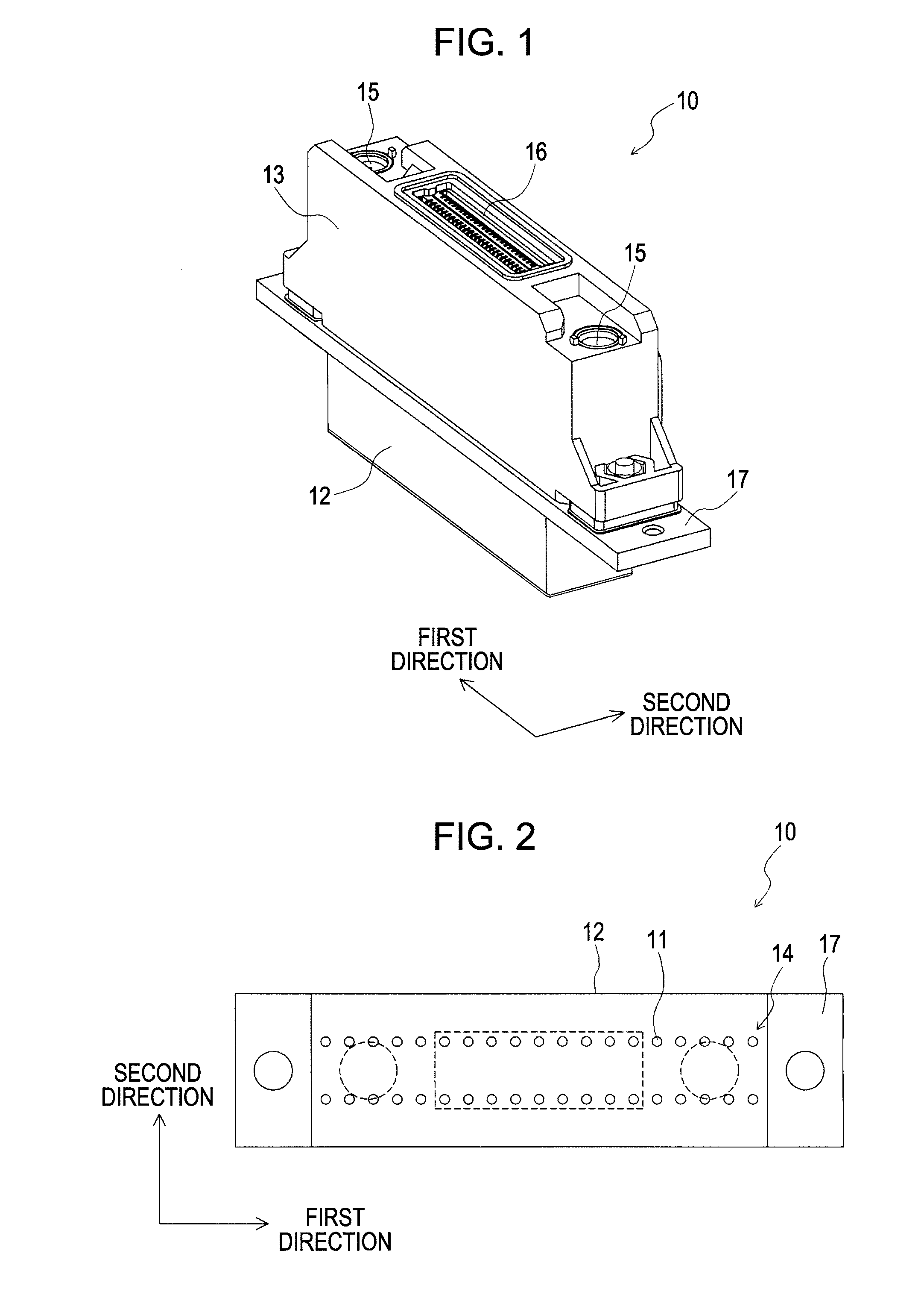
[0032]FIG. 1 is a perspective view showing an ink jet recording head, which is an example of a liquid ejecting head according to a first embodiment of the invention. FIG. 2 is a plan view showing the ink jet recording head.

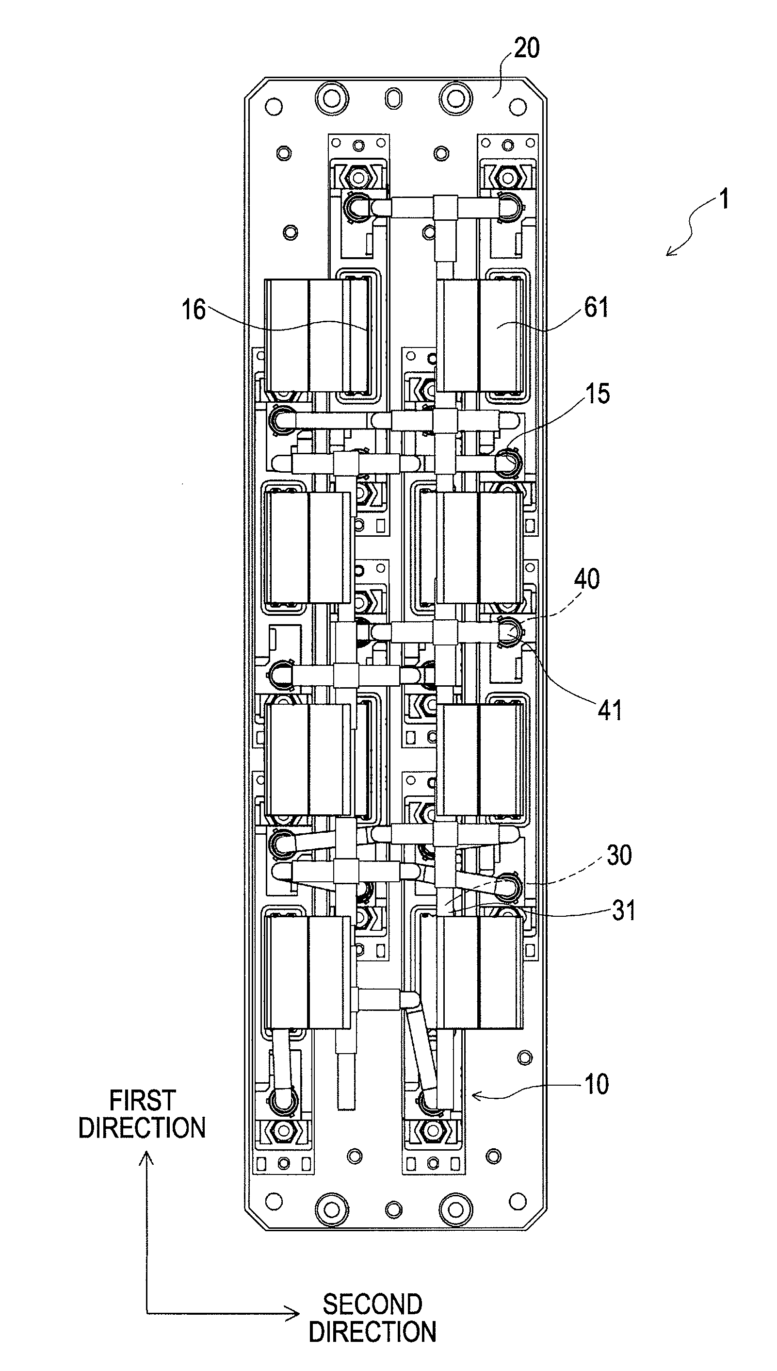
[0033]Referring to the drawings, an ink jet recording head 10 (hereinafter, also referred to as head) according to this embodiment includes a head body 12 having nozzle openings 11 in an end surface, and a passage member 13 fixed to a surface of the head body 12 opposite to the surface with the nozzle openings 11.

[0034]The head body 12 has nozzle arrays 14 each of which has the nozzle openings 11 arranged in a line. The number of nozzle arrays 14 is not particularly limited. For example, a single nozzle array 14 or a plurality of nozzle arrays 14 including two or more arrays may be provided. In this embodiment, a single head body 12 has two nozzle arrays 14. Here, in this embodiment, a first dire...


PUM


Abstract

A liquid ejecting head unit including a plurality of liquid ejecting heads is disclosed. A platform on which the plurality of the liquid ejecting heads are mounted in a staggered arrangement in the first direction, each liquid ejecting head being partially adjacent to each in a second direction, which is orthogonal to first direction. A common trunk passage communicates with the liquid passage ports. A plurality of branch passages communicates with the trunk passage. A plurality of branch circuit wiring sections connects to connectors of the liquid ejecting heads. The plurality of liquid ejecting heads are mounted such that liquid passage ports of each partially adjacent liquid ejecting head are not adjacent to each other in a second direction, and such that the connectors of each partially adjacent liquid ejecting head are not adjacent to each other in the second direction.

Description

[0001]This application claims priority to Japanese Patent Application No. 2008-138772, filed May 27, 2008, and Japanese Patent Application No. 2009-038688, filed Feb. 20, 2009. The entire disclosures of the aforementioned applications are incorporated by reference herein.BACKGROUND OF THE INVENTION[0002]The present invention relates to a liquid ejecting head unit and a liquid ejecting apparatus, in which a plurality of liquid ejecting heads are mounted on a platform, the liquid ejecting heads ejecting liquid from nozzle openings.[0003]A liquid ejecting apparatus represented by an ink jet recording apparatus, such as an ink jet printer or plotter, includes a liquid ejecting head unit (hereinafter, also referred to as head unit) in which a plurality of liquid ejecting heads are mounted, the liquid ejecting heads being capable of ejecting liquid, e.g., ink, reserved in a cartridge or a tank, as liquid droplets.[0004]The plurality of liquid ejecting heads are mounted on a platform, whic...

Claims


Application Information

Patent Timeline
Patent Type & Authority Patents(United States)
IPC IPC(8): B41J2/14
CPCB41J2/145B41J2002/14491B41J2202/20B41J2202/19B41J2/01
Inventor OGUCHI, SATOSHI
Owner SEIKO EPSON CORP
Why Eureka
Try Eureka