Subtitle detection apparatus, subtitle detection method and pull-down signal detection apparatus

a detection apparatus and subtitle technology, applied in the direction of instruments, television systems, color signal processing circuits, etc., can solve the problems of difficult to determine whether the video signal is the pull-down signal or not, the screen brightness would be considerably lower, and the displayed images would not be worth viewing

Inactive Publication Date: 2011-11-22
KK TOSHIBA
View PDF12 Cites 11 Cited by
  • Summary
  • Abstract
  • Description
  • Claims
  • Application Information

AI Technical Summary

Benefits of technology

[0028]According to the embodiment, it is possible to precisely detect a subtitle region in a pull-down signal and to satisfactorily detect a pull-down signal.

Problems solved by technology

If interlaced-scan video signals are directly displayed on the scan lines on such thin TV receivers, the brightness of the screen would considerably lower and displayed images would not be worth viewing.
In the case where a subtitle is included in the pull-down signal, it is difficult to determine whether the video signal is the pull-down signal or not.
Thus, in the prior art, it is not possible to precisely detect a subtitle region and to exactly execute a pull-down interpolation process.

Method used


Image

  • Subtitle detection apparatus, subtitle detection method and pull-down signal detection apparatus
  • Subtitle detection apparatus, subtitle detection method and pull-down signal detection apparatus
  • Subtitle detection apparatus, subtitle detection method and pull-down signal detection apparatus

Examples


first embodiment

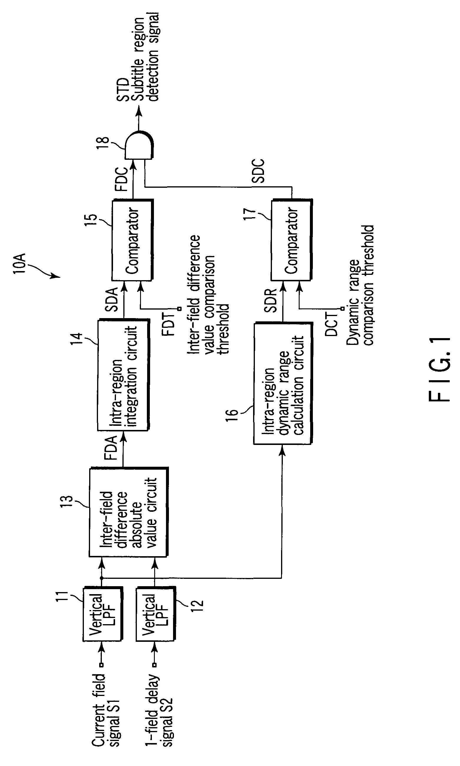
[0030]FIG. 1 is a block diagram that shows the structure of a subtitle detection apparatus 10A according to the present invention.

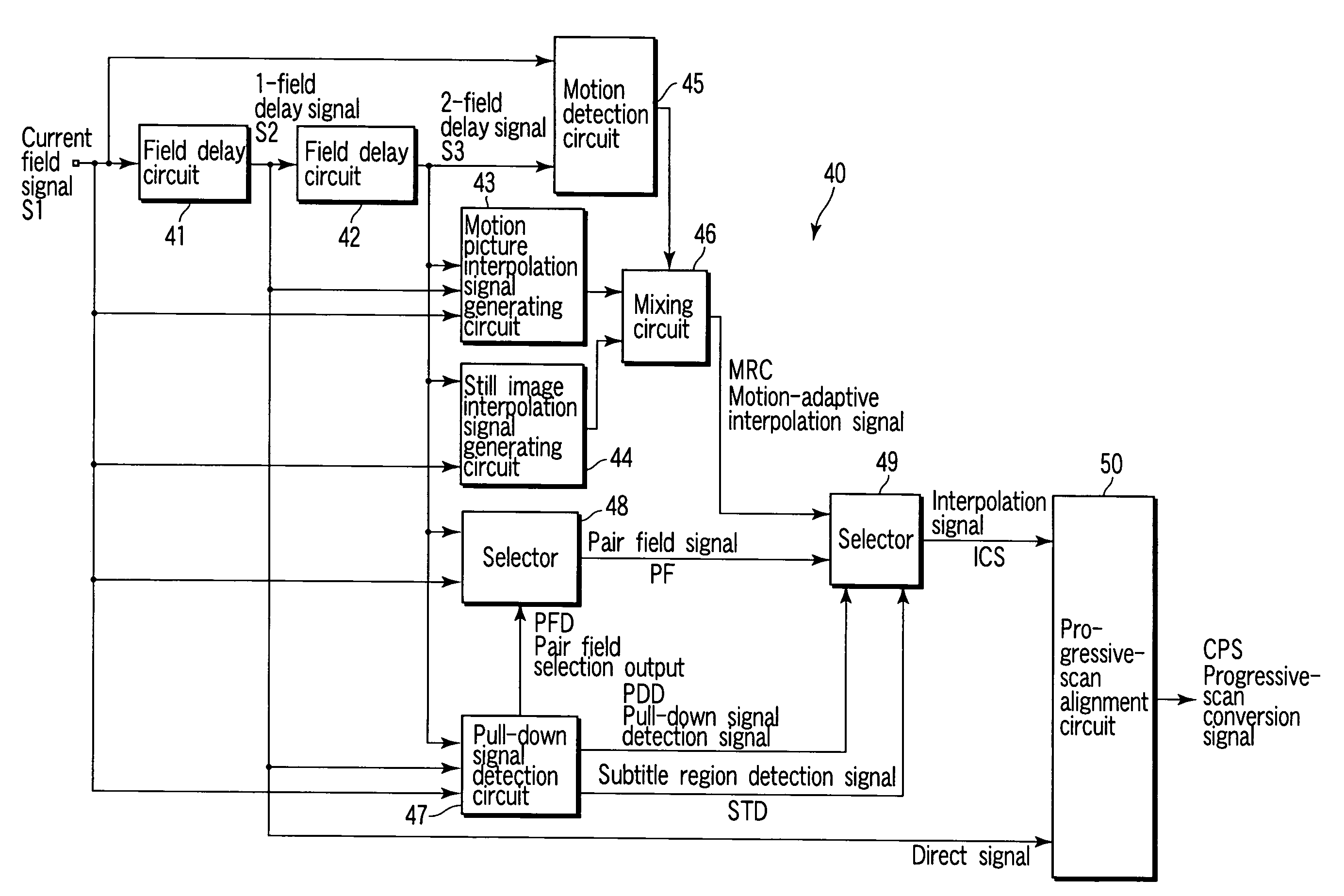
[0031]A current field signal (luminance signal) S1 passes through a first vertical low-pass filter (LPF) 11, and is then input to an inter-field difference absolute value circuit 13 and to an intra-region dynamic range calculation circuit 16. A 1-field delay signal S2 passes through a second vertical LPF 12, and is then input to the inter-field difference absolute value circuit 13. The 1-field delay signal S2 is a signal which is obtained by delaying the current field signal S1 by a 1-field period by using a memory circuit, as will be described later in detail with reference to FIG. 8. The first and second vertical LPFs 11 and 12 remove vertical high-frequency noise in 1 field, and align vertical median points of the current field signal S1 and 1-field delay signal S2. A horizontal LPF may be used for the noise removing filter.

[0032]The inter-field differ...

second embodiment

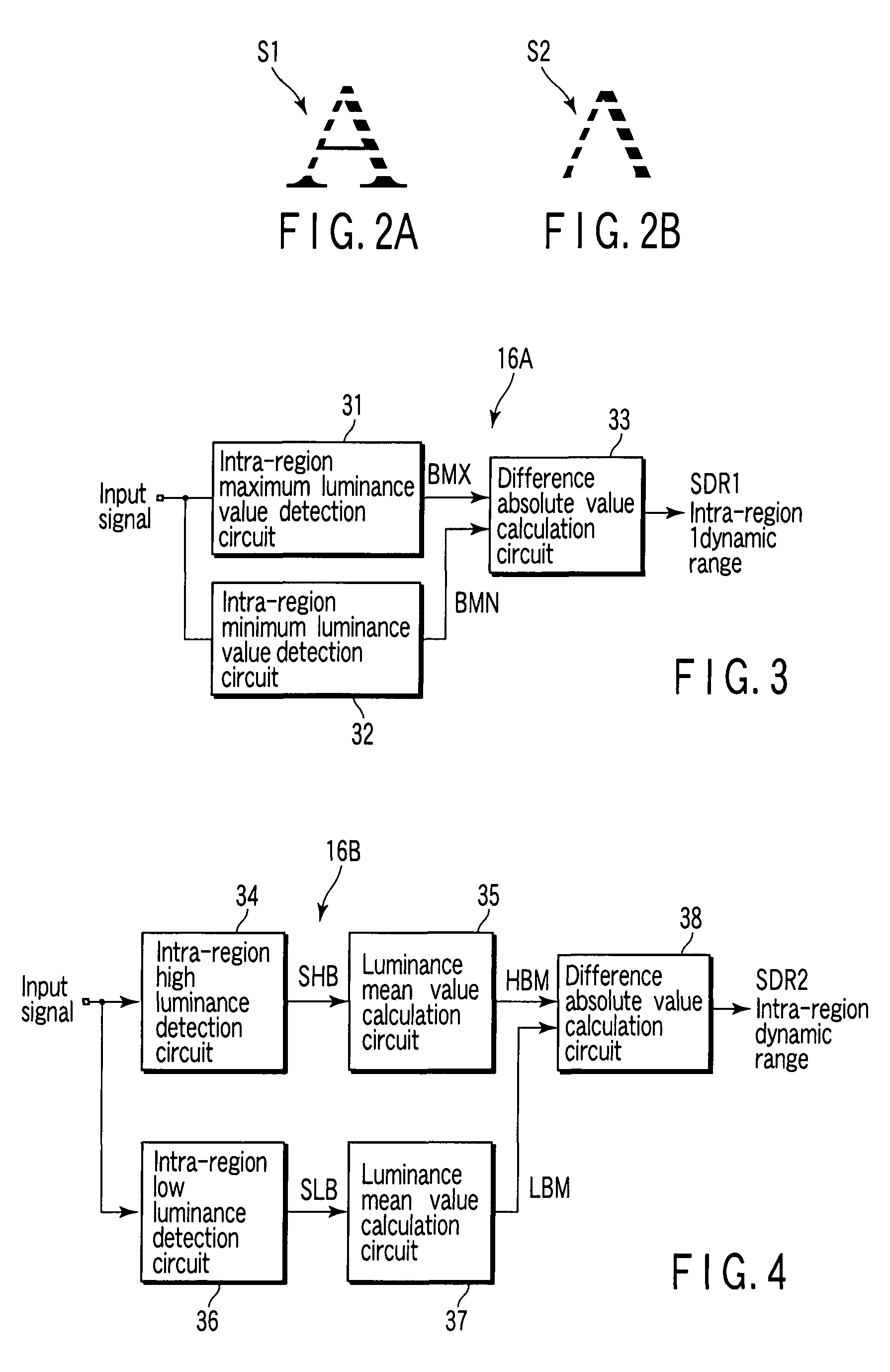
[0040]FIG. 4 shows a dynamic range calculation circuit 16B as the dynamic range calculation circuit 16.

[0041]An intra-region high luminance detection circuit 34 receives the current field signal S1 from the vertical LPF 11, extracts first to n-th high luminance values in the region, and outputs the extracted values as high luminance SHB. A high luminance mean value calculation circuit 35 calculates a mean value HBM of the high luminance SHB. For example, if n is 4, a highest luminance in the region is 100, a second highest luminance in the region is 99, the number of pixels with luminance 100 is 1 and the number of pixels with luminance 99 is 4, the high luminance mean value calculation circuit 35 calculates (100+99*3) / 4 as a high luminance mean value HBM, and outputs 99.25 as the high luminance mean value HBM.

[0042]An intra-region low luminance detection circuit 36 receives the current field signal S1 from the vertical LPF 11, extracts first to n-th low luminance values in the regi...

third embodiment

[0049]FIG. 6 is a block diagram that shows the structure of a subtitle detection apparatus 10C according to the present invention. The subtitle detection apparatus 10C includes a comparator 21 and an intra-region high-luminance-pixel-number counting circuit 22, which are substituted for the dynamic range calculation circuit 16 of the subtitle detection apparatus 10A shown in FIG. 1.

[0050]As described above, in general, a character in a subtitle region is displayed in white with maximum luminance. By the comparator 21, intra-region high-luminance-pixel-number counting circuit 22 and comparator 23, the number of pixels with high luminance in the region is counted and if the number of high-luminance pixels is greater than a comparison threshold value HBT, the region is determined to be a subtitle region.

[0051]The comparator 21 compares the current field signal S1 from the vertical LPF 11 with a luminance level comparison threshold value BLT. If the value of the current field signal S1 ...


PUM


Abstract

An integration circuit divides a screen, which is composed of an input video signal, into regions, integrates absolute values of inter-field differences that are included the respective regions, and provides an intra-region integration value SDA. A dynamic range calculation circuit divides the screen into regions and calculates a dynamic range SDR of luminance in each of the regions. If the intra-region integration value SDA is greater than a comparison threshold value FDT and if the dynamic range SDR of luminance in each of the regions is greater than a comparison threshold value DCT, the region is determined to be a subtitle region.

Description

CROSS-REFERENCE TO RELATED APPLICATIONS[0001]This application is based upon and claims the benefit of priority from Japanese Patent Application No. 2006-083927, filed Mar. 24, 2006, the entire contents of which are incorporated herein by reference.BACKGROUND[0002]1. Field[0003]Embodiments of the present invention relate generally to an apparatus which converts an interlaced-scan video signal to a progressive-scan video signal, and more particularly to an apparatus which detects a subtitle in an interlaced-scan video signal such as a moving picture signal that is generated by 2-3 pull-down or 2-2 pull-down.[0004]2. Description of the Related Art[0005]In the case of an NTSC video signal that is generally used as a TV broadcast signal, a video image is scanned by an interlaced-scan system. In this system, the equivalent number of images per second is increased, and thereby surface flicker is reduced. On the other hand, in recent years, thin TV receivers, such as liquid crystal display ...

Claims


Application Information

Patent Timeline
Patent Type & Authority Patents(United States)
IPC IPC(8): H04N5/14H04N11/20H04N9/64
CPCH04N5/445H04N7/0112H04N7/012H04N7/0137H04N21/4884
Inventor YAMAUCHI, HIMIO
Owner KK TOSHIBA
Why Eureka
Try Eureka