Height adjustable drive arrangement for a floor care machine

a technology for floor care machines and drive arrangements, which is applied in the direction of carpet cleaners, instruments, photosensitive materials, etc., can solve the problems of difficult to construct the adjusting mechanism in such a manner, and achieve the effect of simple manner, reduced production costs, and robust design and construction

Active Publication Date: 2011-12-06
STEIN
View PDF13 Cites 5 Cited by
  • Summary
  • Abstract
  • Description
  • Claims
  • Application Information

AI Technical Summary

Benefits of technology

[0012]With the inventive construction of the drive arrangement, it is possible to use a relatively small number or set of similar parts that can be easily assembled, and that furthermore achieve a trouble-free operation. Furthermore, the inventive drive arrangement provides a self-blocking Cardanic or universal joint that establishes a flexible rotational suspension of the driven head and the floor care disc, with a continuous durable freedom from play, while allowing an angular deflection or “bending” of the rotation axis away from a straight line. Furthermore, with the inventive construction and arrangement of the components, the force transmission through the rolling bodies will be oriented perpendicularly to the helical path of the rolling guides. Appropriate selection of the helical slope angle ensures the proper distribution of the transmitted forces between an axial force component and a rotational force component.
[0013]In order to achieve a compensation of play in the drive arrangement, the two partial elements of the driven element arranged on opposite sides of the spoke elements of the drive element are coupled to one another in a yielding manner by securing elements such as screws or bolts with springs interposed thereon. Thus, these springs allow a slight spring-loaded yielding between the two partial elements of the driven element, so as to compensate any play between the spoke elements and the partial elements of the driven element through the rolling guides and the roller bodies. It is further preferable, that the securing elements and the spring elements are arranged tilted in a direction dependent on the rolling body forces acting on the rolling guides. Particularly, the angle of the securing elements with the spring elements is selected corresponding to the rolling body forces acting on the rolling guides, to achieve the most effective play compensation.
[0014]According to a further advantageous embodiment feature, the rolling guides are fabricated of wear-resistant sintered material, as independent components that are inserted into corresponding receiver recesses in the spoke elements and / or in the partial elements of the driven element. Alternatively, the rolling guides can simply be grooves machined into the spoke elements and the partial elements of the drive element, but it is preferred to embody the rolling guides as removable and replaceable components that can be exchanged for maintenance and repair. An especially simple and advantageous construction is achieved by configuring all of the rolling guides identically as the same identically configured parts for both the drive element and the driven element.

Problems solved by technology

Particularly, it has been found that either the transmission elements of the height adjustable drive arrangement necessary for an automatic height adjustment are not durable or robust enough, or it is difficult to construct the adjusting mechanism in such a manner to achieve a wear-free embodiment with a simple assembly and durable operation.

Method used


Image

  • Height adjustable drive arrangement for a floor care machine
  • Height adjustable drive arrangement for a floor care machine
  • Height adjustable drive arrangement for a floor care machine

Examples


Embodiment Construction

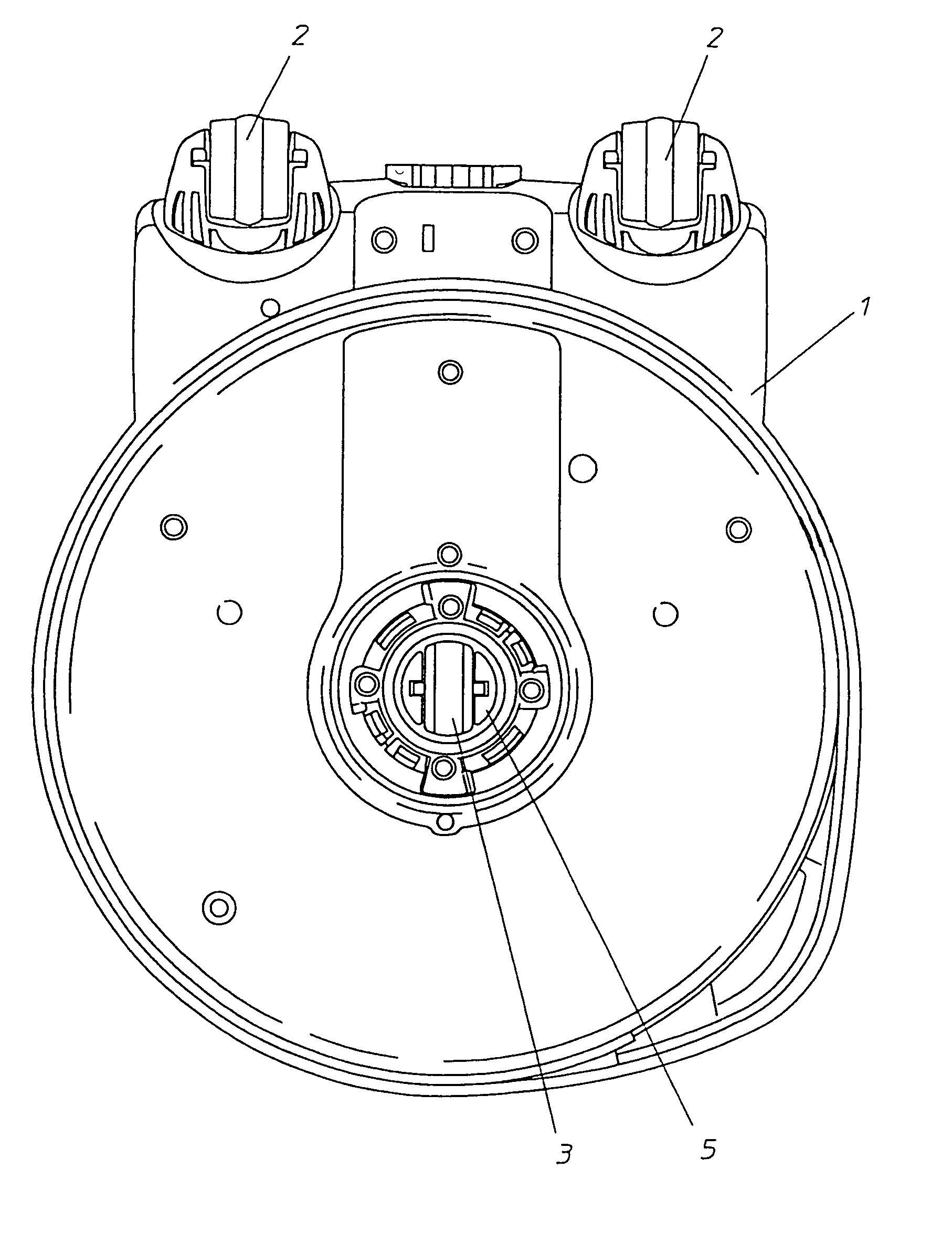
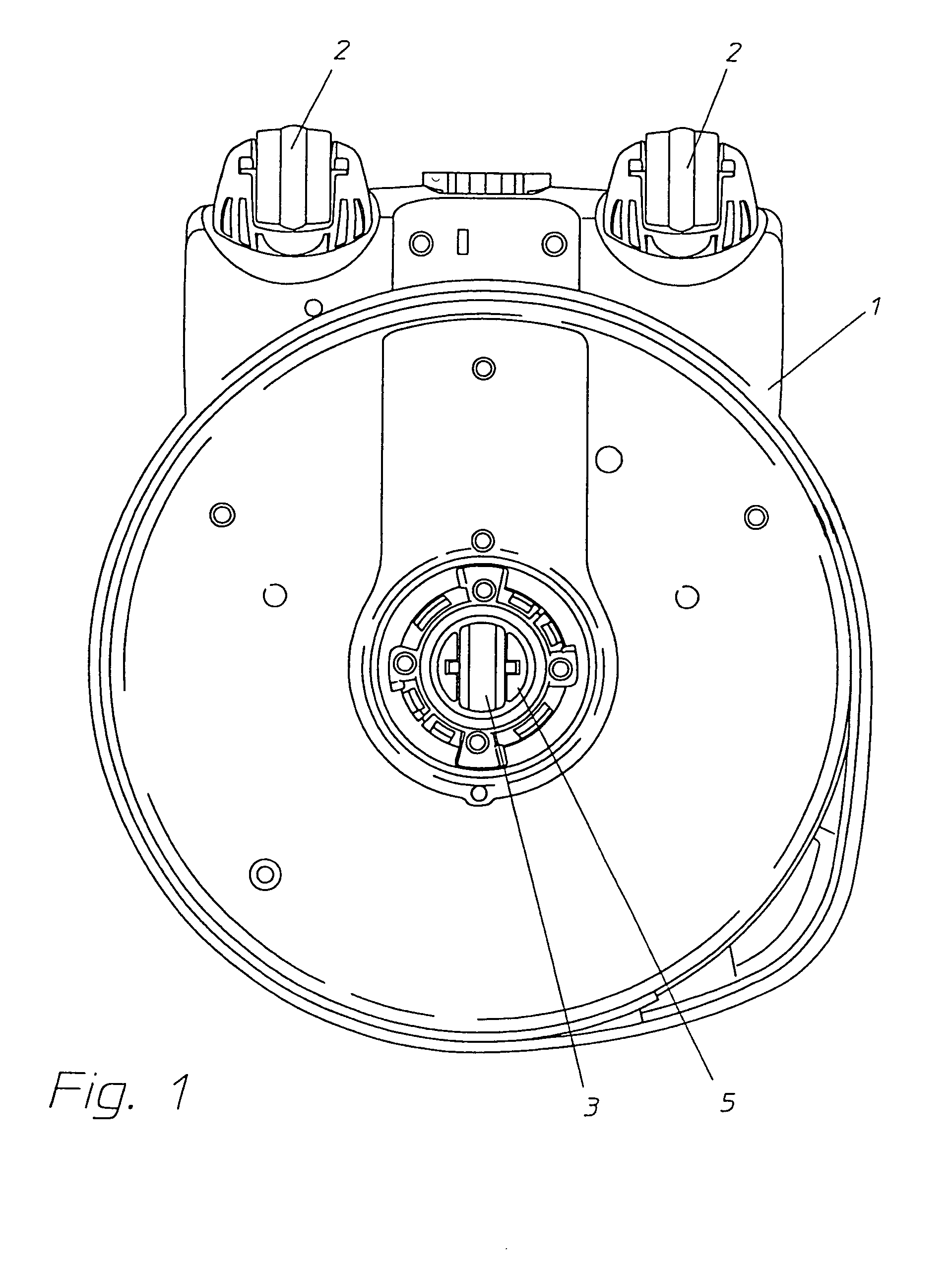
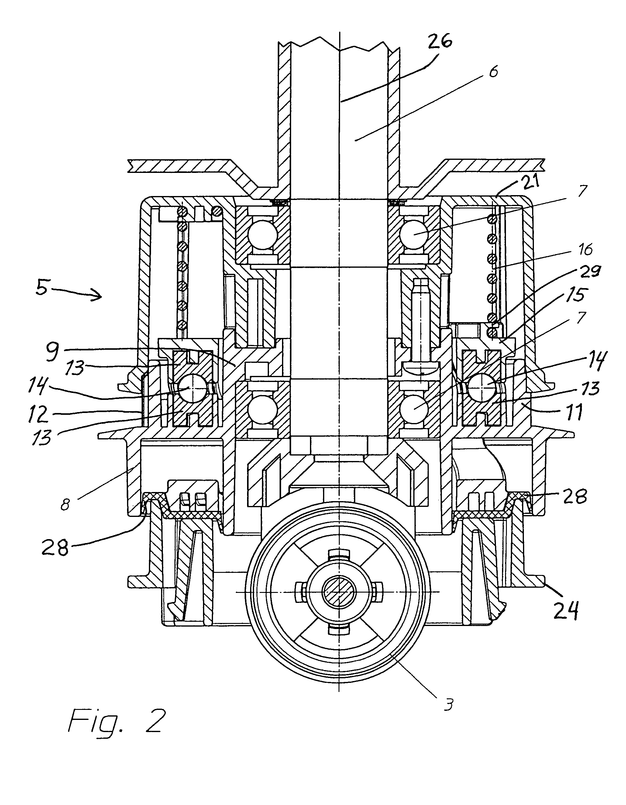
[0026]A floor care machine according to the invention is especially embodied as a floor polishing machine in the present example embodiment. This floor care machine comprises a machine frame or chassis 1 that is supported on a floor surface (not shown) by support and guide elements including running rollers or wheels 2 and a centrally located support roller or wheel 3, which roll along the floor surface to allow the machine to be easily moved. Also, the rollers 2 and 3 support an adjustable portion of the weight of the machine on the floor. The machine further includes a rotationally driven head 24 on which a floor care disc 4 such as a floor polishing pad, a floor brush, a floor sanding disc, or the like can be mounted. Still further, the machine includes a drive motor 22 that is operatively coupled for rotational drive transmission through a transmission element, such as a toothed drive belt 23, and through a height adjustable drive arrangement 5 to the driven head 24 and therewit...


PUM


Abstract

A floor care machine such as a floor polisher includes a machine frame carrying a motor coupled through a drive arrangement to a rotationally driven head on which a floor care disc such as a polishing pad is mounted. The drive arrangement includes a drive element rotationally driven by the motor, and a driven element that is connected to the driven head and is automatically height adjustable. The drive element includes a bearing hub, an outer ring and four uniformly rotationally offset spokes that carry first rolling guides extending along helical paths about the rotation axis. The driven element includes upper and lower partial elements that receive the spokes therebetween and carry second rolling guides arranged facing the first rolling guides along the helical paths, and roller bodies are interposed therebetween. Relative rotation between the drive element and the driven element causes an axial height adjustment of the driven head.

Description

PRIORITY CLAIM[0001]This application is based on and claims the priority under 35 U.S.C. §119 of German Patent Application 10 2007 019 947.5, filed on Apr. 27, 2007, the entire disclosure of which is incorporated herein by reference.FIELD OF THE INVENTION[0002]The invention relates to a floor care machine, such as a floor polishing machine, with a rotatably drivable floor care disc such as a floor polishing pad. The height of the floor care disc is adjustable so as to adjust the pressing force or contact pressure of the floor care disc on the floor, depending on the floor characteristics.BACKGROUND INFORMATION[0003]Floor care machines, such as floor polishing machines, having a rotatably drivable floor care disc are known in the art. Such a conventional floor care machine typically has a machine frame or chassis carrying a drive motor and a drive arrangement that couples the drive motor to the floor care disc, so as to rotationally drive the floor care disc about a vertical rotation...

Claims


Application Information

Patent Timeline
Patent Type & Authority Patents(United States)
IPC IPC(8): B24B27/08
CPCA47L11/16A47L11/4058A47L11/4069B24B7/186B24B41/047
Inventor LIFFERS, ACHIMFALKENSTEIN, BERND
Owner STEIN
Why Eureka
Try Eureka