Unlock instant, AI-driven research and patent intelligence for your innovation.

Shake correction control circuit and image pickup apparatus provided with the same

a control circuit and control circuit technology, applied in the direction of color television details, television system details, television systems, etc., can solve the problems of electric power consumption, difficult to achieve highly accurate correction in electronic shake correction, and inability to correct shak

Active Publication Date: 2012-01-17
SEMICON COMPONENTS IND LLC
View PDF7 Cites 6 Cited by
  • Summary
  • Abstract
  • Description
  • Claims
  • Application Information

AI Technical Summary

Benefits of technology

The patent describes a shake correction control circuit that can switch between optical and electronic shake correction modes. The circuit includes an optical shake correction unit that corrects the optical axis based on vibration detection, an electronic shake correction unit that adjusts the effective region of image signals, and a control unit that switches between the two modes. The technical effect of this invention is to provide a more versatile and effective shake correction solution that can adapt to different camera settings and reduce image blurring.

Problems solved by technology

On the other hand, a plurality of frames are required for the detection of any movement in the electronic shake correction and therefore the shake cannot be corrected if the shake occurs within a single frame.
In the optical shake correction, a mechanical drive mechanism is required for the correction of the lens position which is problematic in terms of the electric power consumed.
If the frame rate is low, highly accurate correction will be difficult to achieve in the electronic shake correction.

Method used


Image

  • Shake correction control circuit and image pickup apparatus provided with the same
  • Shake correction control circuit and image pickup apparatus provided with the same
  • Shake correction control circuit and image pickup apparatus provided with the same

Examples


Embodiment Construction

[0016]The invention will now be described by reference to the preferred embodiments. This does not intend to limit the scope of the present invention, but to exemplify the invention.

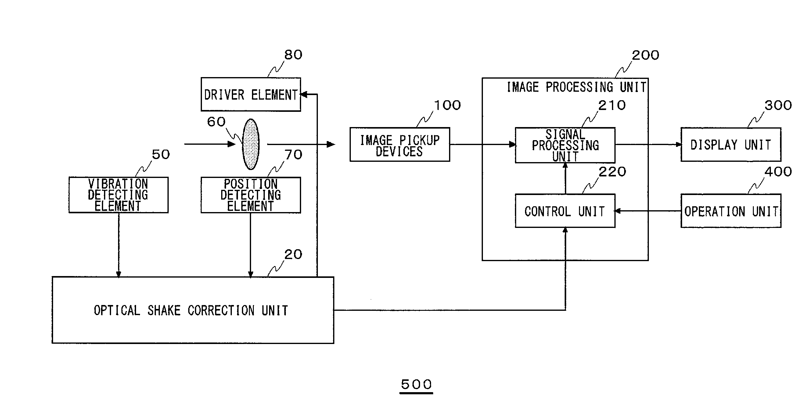
[0017]FIG. 1 is a block diagram showing a structure of an image pickup apparatus 500 according to an embodiment of the present invention.

[0018]The image pickup apparatus 500 includes a lens 60, a driver element 80, a position detecting element 70, a vibration detecting element 50, an optical shake correction unit 20, image pickup devices 100, an image processing unit 200, a display unit 300, and an operation unit 400.

[0019]The driver element 80 drives the lens 60. The position detecting element 70 detects the position of the lens 60. The vibration detecting element 50 detects the vibration applied to the image pickup apparatus 500.

[0020]The optical shake correction unit 20 corrects the position of the lens 60 by controlling the driver element 80 in response to an output signal of the vibration detecting ...


PUM


Abstract

An optical shake correction unit corrects an optical axis in response to an output signal of an vibration detecting element. An electronic shake correction unit adaptively varies an effective region in image signals of an image pickup region formed by image pickup devices. A control unit performs control such that either the optical shake correction unit or the electronic shake correction unit is enabled by switching between a first image pickup mode and a second image pickup mode.

Description

CROSS-REFERENCE TO RELATED APPLICATIONS[0001]This application is based upon and claims the benefit of priority from the prior Japanese Patent Application No. 2007-327852, filed on Dec. 19, 2007, the entire contents of which are incorporated herein by reference.BACKGROUND OF THE INVENTION[0002]1. Field of the Invention[0003]The present invention relates to a shake correction control circuit provided with a function for correcting vibration such as one caused by camera shake, and an image pickup apparatus that includes said shake correction control circuit.[0004]2. Description of the Related Art[0005]Digital still cameras and digital movie cameras (hereinafter generically referred to as digital cameras) have been widely used by general users. Various methods for correcting camera shake are proposed for users who are not familiar with how to handle the cameras properly and therefore are likely to encounter camera shake when taking pictures. Among those digital cameras available, there ...

Claims


Application Information

Patent Timeline
Patent Type & Authority Patents(United States)
IPC IPC(8): H04N5/228H04N23/40
CPCH04N5/23248H04N5/23258H04N5/23267H04N5/23274H04N23/6842H04N23/683H04N23/68H04N23/6812
Inventor NAKAKUKI, TOSHIOWATANABE, TOMOFUMI
Owner SEMICON COMPONENTS IND LLC