Ambulance cot system

a technology for cots and cots, applied in the field of cot systems and cots, can solve the problems of obesity, a leading public health problem,

Active Publication Date: 2012-04-10
FERNO WASHINGTON
View PDF27 Cites 44 Cited by
  • Summary
  • Abstract
  • Description
  • Claims
  • Application Information

AI Technical Summary

Benefits of technology

[0013]The present invention also provides an ambulance cot (e.g., a manual cot or a hydraulically powered cot) comprising a telescoping leg assembly comprising a roller bearing system. In some embodiment, the telescoping leg assembly comprising a roller bearing system comprises both a main, outer rail and an inner rail. In some embodiments, the main rail comprises a top side and bottom side, wherein the top side of the main rail comprises an extruded portion fastened to the main rail that comprises a roller bearing, wherein the roller bearing rolls along the top side of the inner rail (e.g., when the telescoping leg assembly is expanded (e.g., when the cot is raised) or contracted (e.g., when a cot is lowered or collapsed). In some embodiments, a cot comprises two telescoping leg assemblies (e.g., with each comprising a roller bearing system) that are parallel to each other wherein the main rails of each telescoping leg assembly are fastened to each other via a cross tube that is irremovably attached to each of the extruded portions of the main rails. In some embodiments, a cot comprises four telescoping leg assemblies (e.g., with each comprising a roller bearing systems). In some embodiments, the inner rail comprises a top side and a bottom side, wherein one or more roller bearings (e.g., two, three, four or more) are connected to a top portion and one or more roller bearings (e.g., two, three, four or more) are connected to a bottom portion of the inner leg, wherein the roller bearings roll along the inside face of the top side of the main rail and the inside face of the bottom side of the main rail when the telescoping leg is expanded (e.g., when a cot is raised) or contracted (e.g., when a cot is lowered or collapsed). In some embodiments, the roller bearing system reduces frictional force of the telescoping legs (e.g., the frictional force associated with an increase or decrease in length of the telescoping legs (e.g., that occurs with raising or lowering of the cot). In some embodiments, reducing frictional force of the telescoping legs reduces hydraulic system pressure. In some embodiments, reducing frictional force of the telescoping legs reduces battery current draw. In some embodiments, reducing frictional force of the telescoping legs extends the usable life of the cot (e.g., by reducing hydraulic system pressure and / or reducing battery current draw).
[0016]The present invention also provides an ambulance cot comprising a pair of fixed length legs and a pair of telescoping legs, wherein the telescoping legs comprise a roller bearing system. In some embodiments, the roller bearing system comprises a main rail and an inner rail, wherein the inner rail telescopingly moves along and outward from within the main rail, wherein the main rail comprises one or more roller bearings that contact and roll along an outside face of the inner rail. In some embodiments, the one or more roller bearings are attached to an extruded portion of the main rail and contact and roll along the topside of the inner rail. In some embodiments, the inner rail comprises one or more roller bearings that contact and roll along the inside face of the top side and one or more roller bearings that contact and roll along the inside face of the bottom side of the main rail. In some embodiments, the roller bearing system reduces frictional force generated during increasing or decreasing the length of the telescoping legs. In some embodiments, the friction force is associated with raising and / or lowering of a subject upon the cot. In some embodiments, reducing the frictional force reduces energy required to raise and / or lower the cot. In some embodiments, the energy is drawn from batteries utilized to power a hydraulic system configured to raise and / or lower the pair of fixed length legs and the pair of telescoping legs. In some embodiments, the fixed length legs are parallel to each other and pivotally connect to a foot-end cross tube of a base frame and a head-end cross tube of a top frame of the cot. In some embodiments, the fixed-length legs reduce hydraulic system pressure during raising of the cot.

Problems solved by technology

The prevalence of overweight and obesity in the United States makes obesity a leading public health problem.

Method used


Image

  • Ambulance cot system
  • Ambulance cot system
  • Ambulance cot system

Examples


Embodiment Construction

[0108]The present invention relates to ambulance cots, cot systems and methods of using the same. In particular, the present invention provides an ambulance cot comprising a hydraulic system and a tip angle monitoring, recording and alert system, and methods of using the same (e.g., to transport subjects and / or to detect and / or record operational data related to cot usage).

[0109]The following embodiments are provided by way of example and are not intended to limit the invention to these particular configurations. Numerous other applications and configurations will be appreciated by those of ordinary skill in the art.

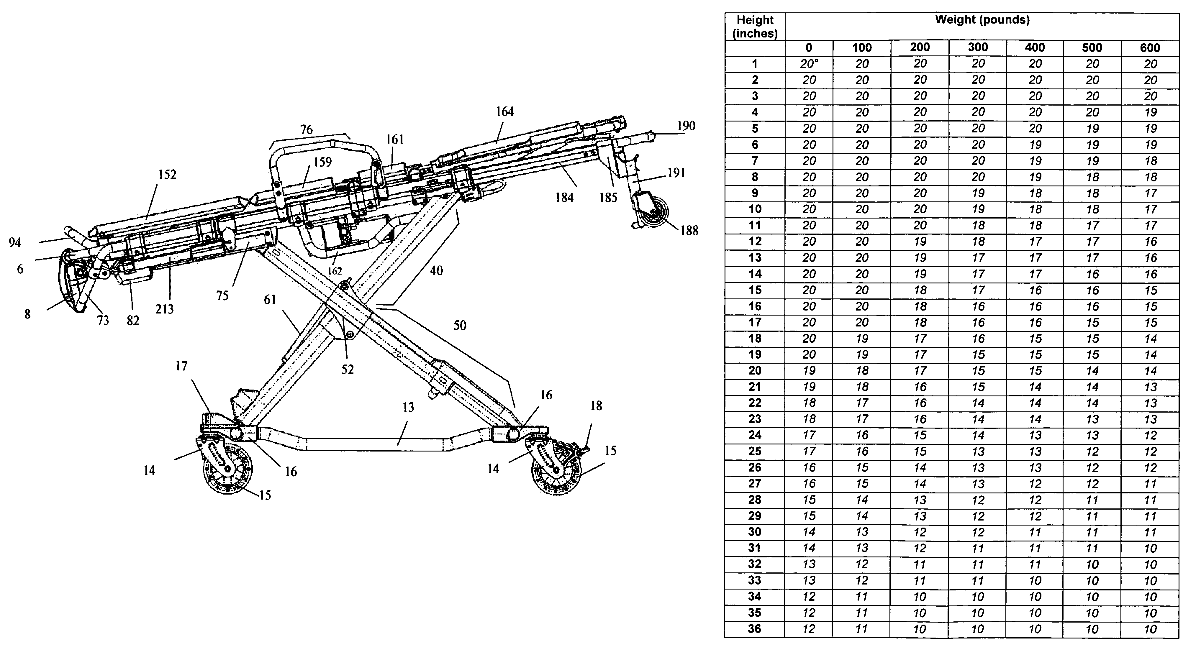
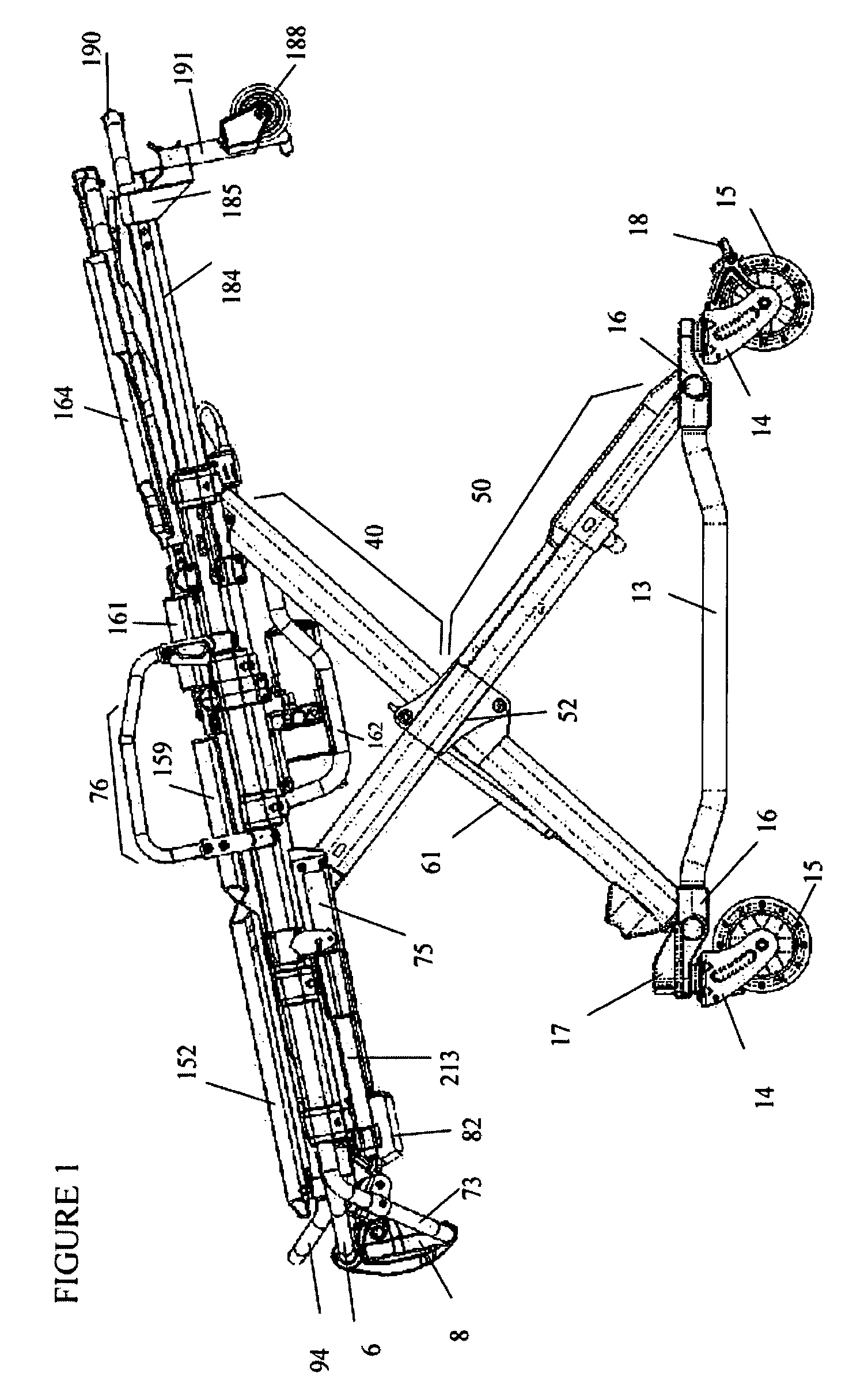
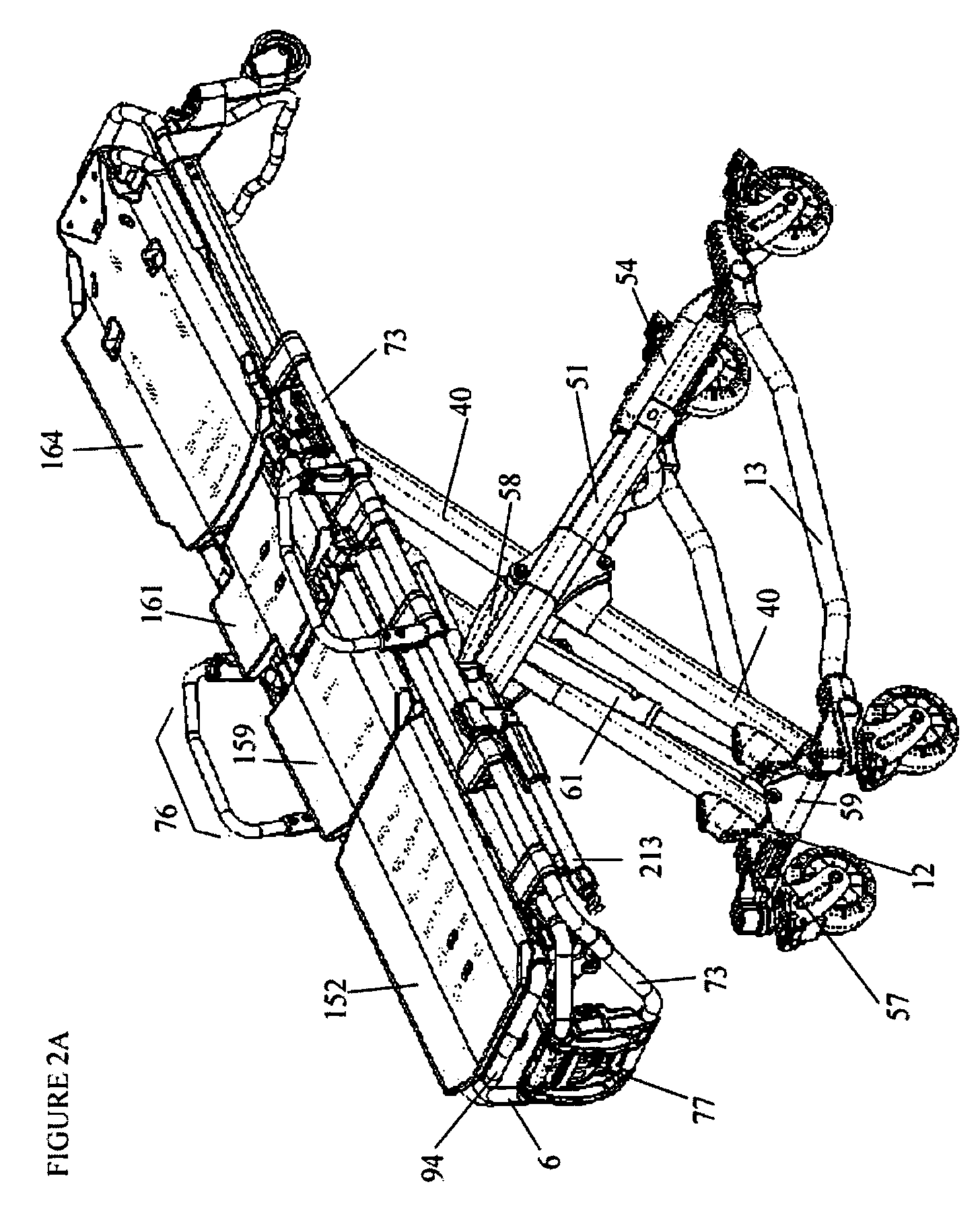
[0110]An ambulance cot system of the present invention is depicted in the drawings. For example, an ambulance cot system 1 embodied by the invention is shown in FIGS. 1-52. In some embodiments, the ambulance cot system 1 comprises a pair of frames comprising a base frame 10 and a top frame 74 as shown, for example, in FIGS. 1 and 2. The base frame 10 includes a foot-end ...


PUM


Abstract

The present invention relates to ambulance cots, cot systems and methods of using the same. In particular, the present invention provides an ambulance cot comprising a hydraulic system and a tip angle monitoring, recording and alert system, and methods of using the same (e.g., to transport subjects and / or to detect and / or record operational data related to cot usage).

Description

[0001]This application is a continuation-in-part of U.S. patent application Ser. No. 11 / 968,013, filed 31 Dec. 2007, hereby incorporated by reference in its entirety.FIELD OF THE INVENTION[0002]The present invention relates to ambulance cots, cot systems and methods of using the same. In particular, the present invention provides an ambulance cot comprising a hydraulic system and a tip angle monitoring, recording and alert system, and methods of using the same (e.g., to transport subjects and / or to detect and / or record operational data related to cot usage).BACKGROUND OF THE INVENTION[0003]The prevalence of overweight and obesity in the United States makes obesity a leading public health problem. The United States has the highest rates of obesity in the developed world. From 1980 to 2002, obesity doubled in adults and overweight prevalence tripled in children and adolescents (See, e.g., Ogden et al., JAMA 295 (13): 1549-55). From 2003-2004, of “children and adolescents aged 2 to 19 ...

Claims


Application Information

Patent Timeline
Patent Type & Authority Patents(United States)
IPC IPC(8): G01C9/06G06F17/40A61G7/018
CPCA61G1/013A61G7/0507B60T1/04B60T7/04B60T7/10B62B5/04G01C9/00A61G1/0262A61G1/0212A61G1/0287A61G1/0293A61G1/0243A61G1/0567A61G2203/44A61G2007/0513A61G2007/0527A61G2200/16A61G2203/34A61G2203/40A61G2210/30B62B5/0433B62B5/0438B62B5/0485A61G2001/042A61G2203/42A61G1/042A61G7/0513A61G7/0527
Inventor REED, JAIME C.KRIEGER, JEFFREY J.SEIZER, RICHARD T.BHEND, SHAWN G.SULIK, JAROD M.
Owner FERNO WASHINGTON
Why Eureka
Try Eureka