Wireless transceiver within an electrical receptacle system

a transceiver and electrical receptacle technology, applied in the field of electrical receptacles, can solve the problems of radios being easily tampered, radio repeaters being installed in large areas, and time-consuming, and achieve the effects of improving radio network layout, rapid retrofitting or replacement, and dramatically reducing installation times

Active Publication Date: 2012-05-08
SCHNEIDER ELECTRIC USA INC
View PDF36 Cites 23 Cited by
  • Summary
  • Abstract
  • Description
  • Claims
  • Application Information

AI Technical Summary

Benefits of technology

[0004]The proposed electrical receptacle system incorporates a wireless transceiver and an antenna into a standard electrical receptacle or faceplate. Installation times are dramatically reduced because a separate power connection is not required to be installed to power the transceiver electronics. Existing electrical receptacles, faceplates, or junction boxes can be quickly retrofitted or replaced with the new electrical receptacle system disclosed herein. A better radio network layout with improved coverage can be achieved because there are fewer restrictions on where the electrical receptacle systems can be placed. Electrical receptacles are visually acceptable in open, visible areas. Network reliability is increased because the proposed electrical receptacle system eliminates the possibility of tampering with or unplugging the radio components. Placement of an integrated antenna in the receptacle housing or faceplate can be leveraged with the dimensions of junction boxes to better direct and amplify the wireless signals. Electrical design can be simplified or isolation requirements can be more easily met if there is no way for the user to contact any part of the circuit powering the wireless components.

Problems solved by technology

Installation of radio repeaters in large, open areas is a time-consuming process that requires separate power connections to power each radio.
When batteries are not an option, unsightly power cords to power each radio must be plugged into an electrical outlet and run to the radio.
These radios are also susceptible to tampering, particularly when installed in public areas, and theft.

Method used


Image

  • Wireless transceiver within an electrical receptacle system
  • Wireless transceiver within an electrical receptacle system
  • Wireless transceiver within an electrical receptacle system

Examples


Embodiment Construction

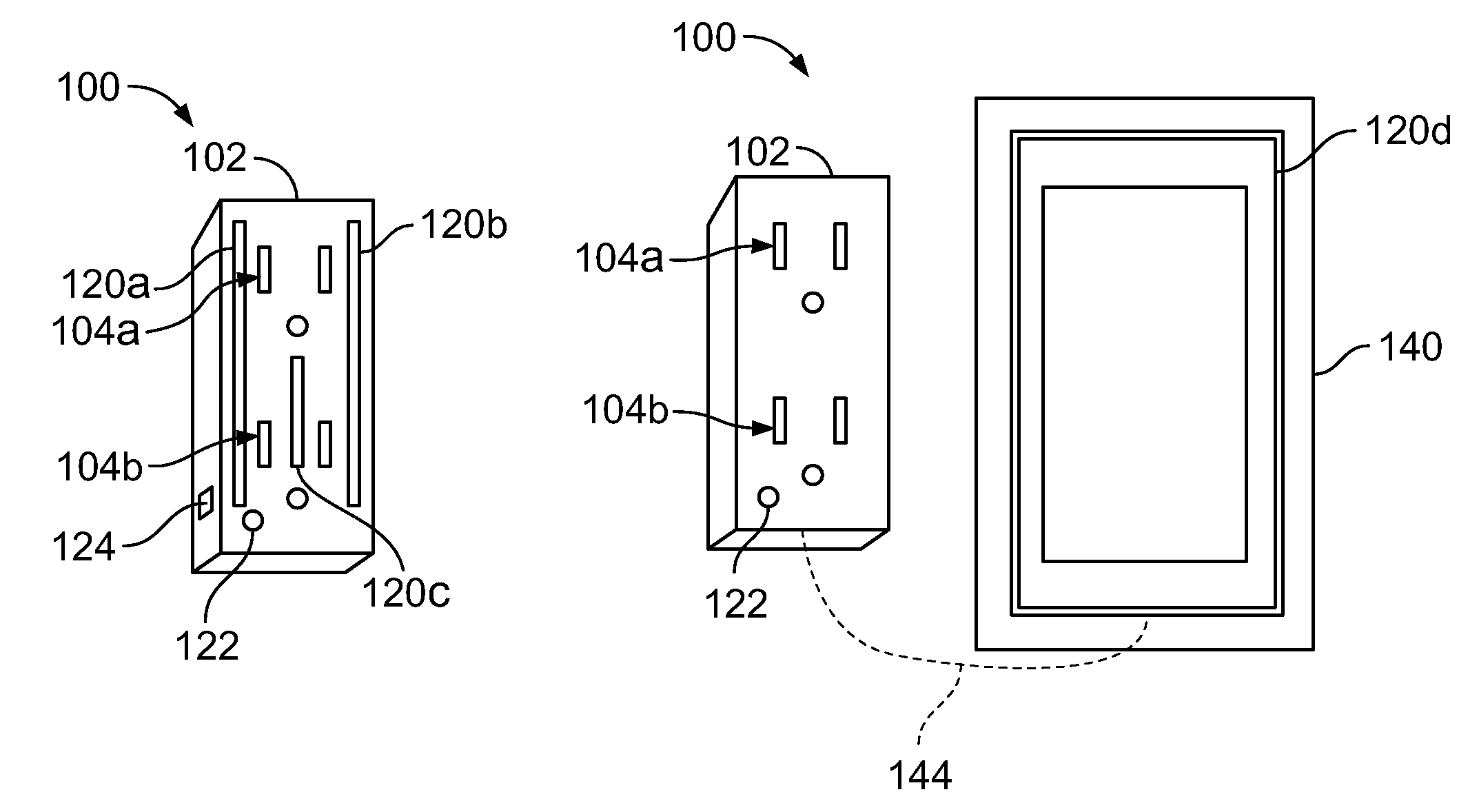
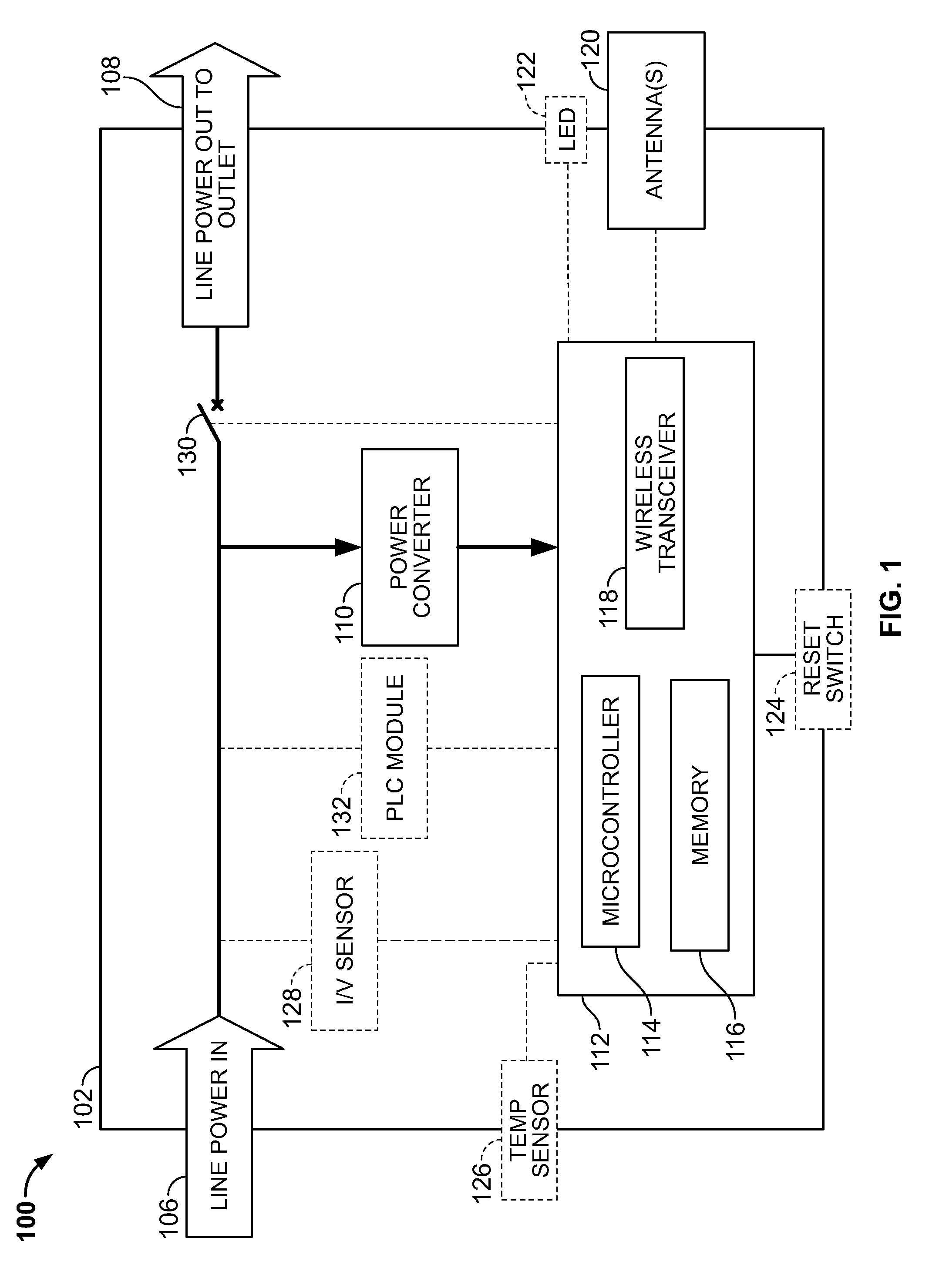
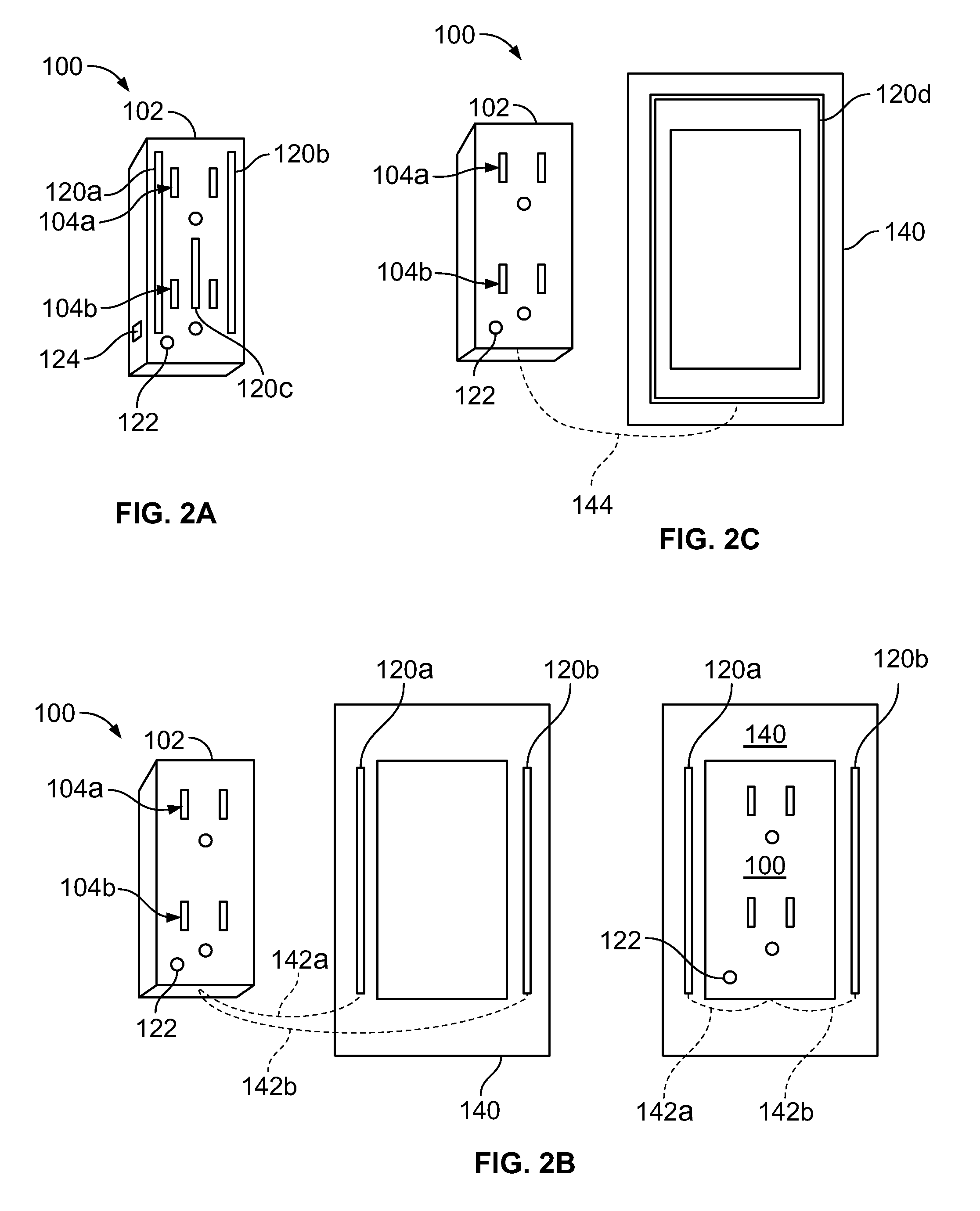
[0021]Turning now to FIG. 1, a functional block diagram of a wall-mounted electrical receptacle assembly 100 is shown. By “wall-mounted,” it is meant to refer to electrical receptacles that are mounted flush against a surface, such as a wall, a ceiling, a floor, or a post. Such electrical receptacles are typically surrounded by a faceplate 140 (see FIG. 2B) and are mounted to a junction box positioned behind the wall, ceiling, floor, or post so that the faceplate 140 is flush against the surface of the wall, ceiling, floor, or post. The electrical receptacle assembly 100 includes a housing 102 that houses a number of electronic components. A line power input 106 carries line power from the electrical wiring to the electrical receptacle assembly 100 and is received in the housing 102 thereof. A line power output 108 carries the line power to an electrical socket or outlet that conventionally receives an external power plug. It should be noted that the electrical receptacle assembly 1...


PUM


Abstract

An electrical receptacle assembly having a housing that includes a wireless transceiver electrically coupled to one or more antennas that can be integrated into the receptacle housing itself or in the receptacle's faceplate. The one or more antennas can be one or more dipoles or a single loop antenna. The housing also houses a power converter that derives its power directly from the line connection to the outlet. A junction box includes an integrated antenna reflector for improved radio direction and propagation relative to the antenna(s). Or, an antenna reflector insert is placed within the junction box behind the electrical receptacle assembly. The electrical receptacle assembly further includes a temperature sensor, a PLC module, or a current / voltage sensor and communicates associated data via its wireless transceiver. A status indicator is disposed on the front of the housing. A reset switch on housing resets the electronics to a default state.

Description

FIELD OF THE INVENTION[0001]Aspects disclosed herein relate generally to electrical receptacles, and, more particularly, to a wireless transceiver integrated into an electrical receptacle or a receptacle face plate.BACKGROUND[0002]Installation of radio repeaters in large, open areas is a time-consuming process that requires separate power connections to power each radio. When batteries are not an option, unsightly power cords to power each radio must be plugged into an electrical outlet and run to the radio. It can be preferable to install the radios in locations where they are as visually unobtrusive as possible, relegating the radios to hallways, corridors, or ceilings where their radio transmission is less effective. These radios are also susceptible to tampering, particularly when installed in public areas, and theft.[0003]What is needed, therefore, is a wireless transceiver that is integrated within an electrical receptacle assembly. The present disclosure is directed to addres...

Claims


Application Information

Patent Timeline
Patent Type & Authority Patents(United States)
IPC IPC(8): H04B7/00
CPCH01R13/66H04B3/542H04B2203/5441H04B2203/5454
Inventor SCHUBERT, CLIFFORD
Owner SCHNEIDER ELECTRIC USA INC
Why Eureka
Try Eureka