Battery arrangement

a battery arrangement and battery technology, applied in the field of battery arrangement, can solve the problems of limited control of cooling air flow, adverse effect of battery arrangement, etc., and achieve the effect of small installation space requirement, increased power of battery arrangement of invention, and effective elimination

Inactive Publication Date: 2012-06-26
DR ING H C F PORSCHE AG
View PDF68 Cites 19 Cited by
  • Summary
  • Abstract
  • Description
  • Claims
  • Application Information

AI Technical Summary

Benefits of technology

[0012]The disposition of the battery cell packs one above the other, enables a battery arrangement with a relatively small installation space requirement. The interposed tunnel simultaneously ensures that the cooling air flow passes uniformly through both battery cell packs so that the battery cell packs are cooled uniformly. Different levels of cooling, as known for example from the prior art, therefore are eliminated effectively. As a result, the power of the battery arrangement of the invention can be increased.

Problems solved by technology

The three battery cell packs are arranged adjacent to one another and, due to that adjacent arrangement, are subjected to different levels of cooling, which can have an adverse effect on the power of the battery arrangement.
However, the control of the cooling air flow is only effective to a limited extent.

Method used


Image

  • Battery arrangement
  • Battery arrangement

Examples


first embodiment

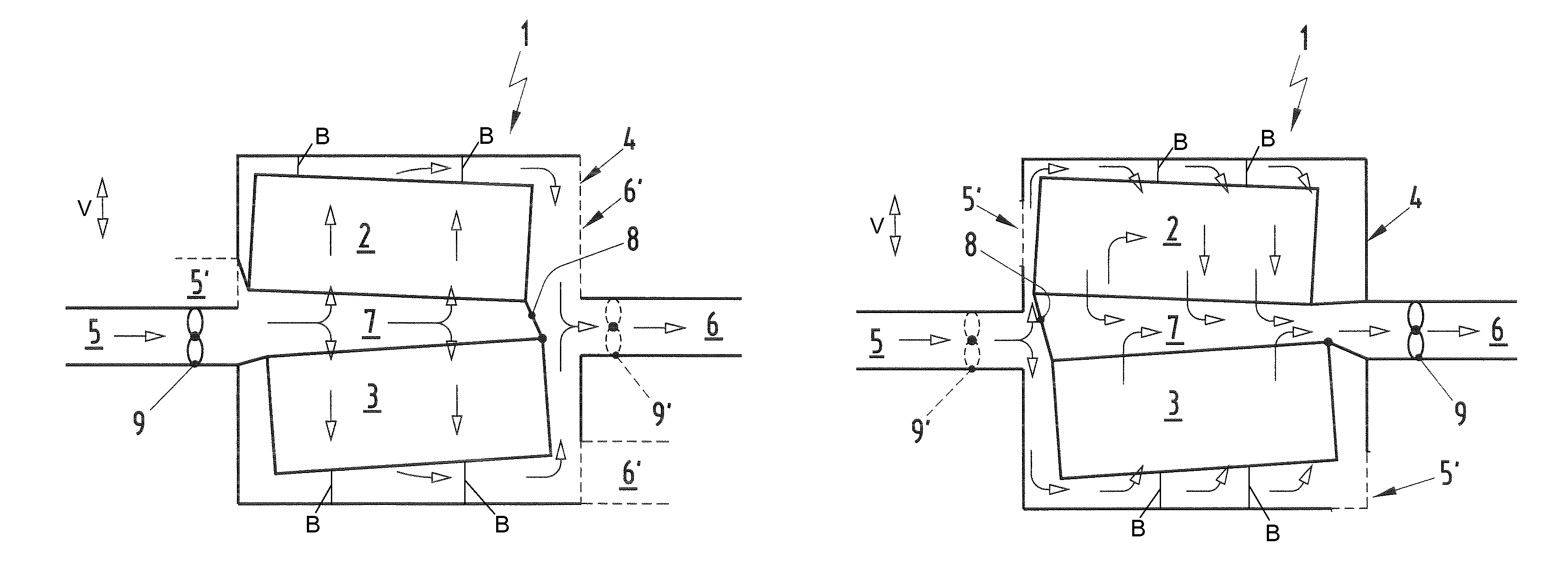
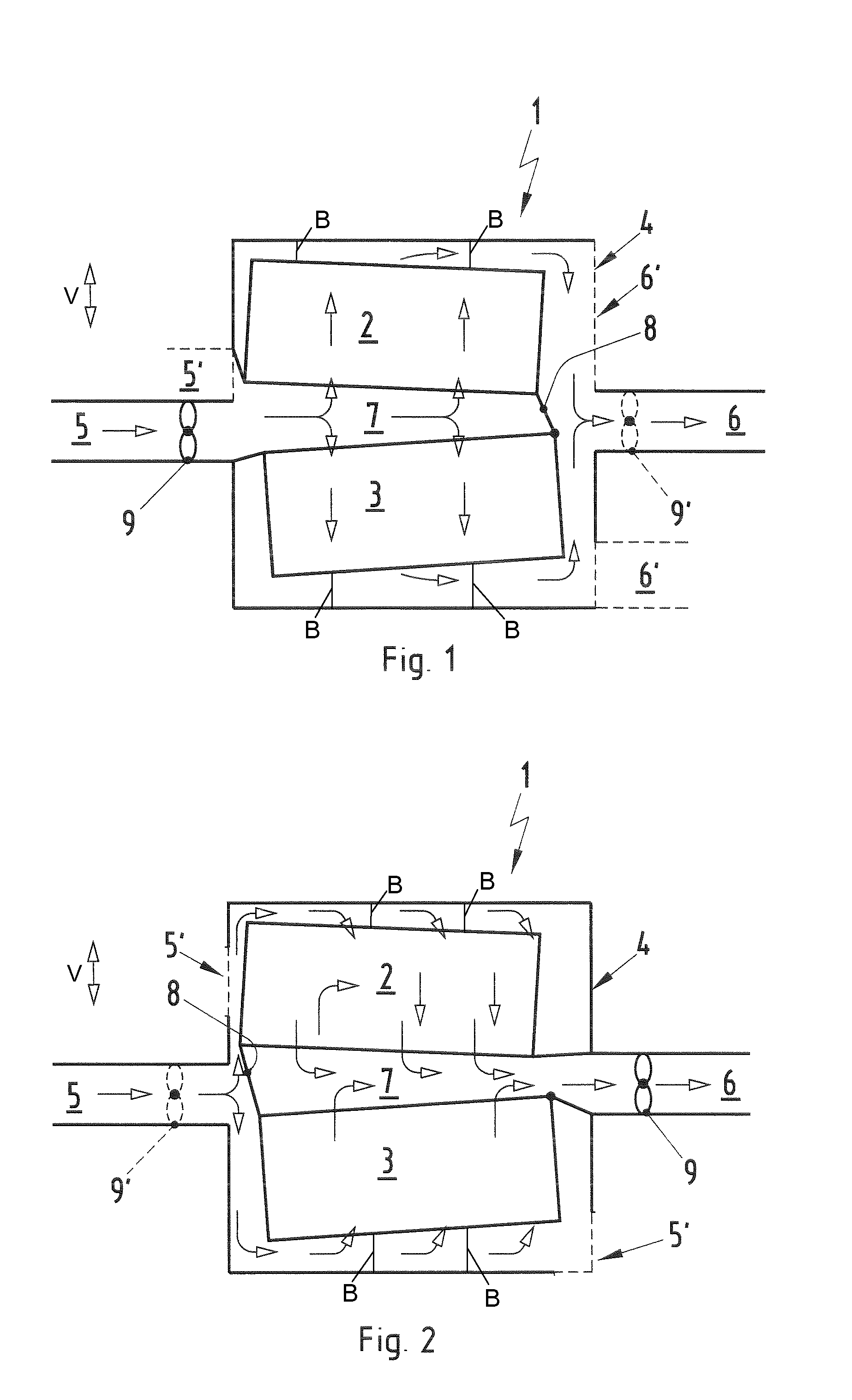
[0019]A battery arrangement in accordance with the invention is identified generally by the numeral 1 in FIG. 1. The battery arrangement 1 has two battery cell packs 2 and 3 arranged together in a battery housing 4 so that the battery housing 4 surrounds the battery cell packs 2 and 3. The battery housing 4 has at least one first opening 5 for supplying cooling air and at least one second opening 6 for the discharging heated air. Further first openings 5′ or second openings 6′ may be provided and are illustrated by dashed lines in FIGS. 1 and 2. However, reference always is made herein to one first opening 5 and one second opening 6 for better comprehensibility.

[0020]The two battery cell packs 2 and 3 are arranged one above the other and are spaced apart from one another in the vertical direction V. Thus, the two battery cell packs 2 and 3 delimit, in terms of height, an interposed tunnel 7.

[0021]The battery arrangement 1 of the first embodiment of the invention has the first openin...

second embodiment

[0022]A second alternate embodiment of the invention is illustrated in FIG. 2 and has at least the second opening 6 arranged at the same level as the tunnel 7. The tunnel of the second embodiment is closed off at a side facing toward the first opening 5 provides direct communication to the second opening 6. Thus, cooling air flows in through the first opening 5, into the space between the battery cell packs 2, 3 and the battery housing 4, through the battery cell packs 2, 3, into the tunnel 7 and out again via the second opening 6.

[0023]Both embodiments have the great advantage that a cooling air flow passes uniformly through both battery cell packs 2 and 3, and hence both battery cell packs 2 and 3 are cooled uniformly. The arrangement of the two battery cell packs 2 and 3 one above the other enables a relatively dense packaging and a small footprint with a corresponding decisive advantage. More particularly, the battery arrangement 1 requires only a comparatively small installatio...


PUM

PropertyMeasurementUnit
heightaaaaaaaaaa
voltageaaaaaaaaaa
poweraaaaaaaaaa

Abstract

A battery arrangement (1) has at least two battery cell packs (2, 3) arranged in a common battery housing (4). The battery housing (4) has at least one first opening (5) for supplying cooling air and at least one second opening (6) for discharging heated air. The battery cell packs (2, 3) are arranged one above the other and delimit a tunnel (7) therebetween in a height direction. At least one of the first and second openings (5, 6) is arranged substantially at the same level as the tunnel (7). The tunnel (7) is closed at a side facing one of the first and second openings (5, 6) so that air flowing between the first and second openings (5, 6) is channeled through or around the battery cell packs (2, 3).

Description

CROSS-REFERENCE TO RELATED APPLICATIONS[0001]This application claims priority under 35 USC 119 to German Patent Application No. 10 2008 051 085.8 filed on Oct. 9, 2008, the entire disclosure of which is incorporated herein by reference.BACKGROUND OF THE INVENTION[0002]1. Field of the Invention[0003]The invention relates to a battery arrangement with at least two battery cell packs and to a hybrid vehicle fitted with such a battery arrangement.[0004]2. Description of the Related Art[0005]U.S. Pat. No. 7,017,361 discloses a generic battery arrangement with three battery cell packs arranged in a common battery housing. The battery housing has a first opening for supplying cool air and a second opening for discharging heated air. The three battery cell packs are arranged adjacent to one another and, due to that adjacent arrangement, are subjected to different levels of cooling, which can have an adverse effect on the power of the battery arrangement.[0006]JP 2001 10 58 94 A and JP 08 31...

Claims


Application Information

Patent Timeline
Patent Type & Authority Patents(United States)
IPC IPC(8): B60R16/04B60K11/00H01M10/50H01M50/204
CPCB60K6/28H01M2/1077H01M10/4207H01M10/5073H01M10/5016H01M10/5067H01M10/5004H01M10/625H01M10/6563H01M10/6566H01M10/613Y02E60/10H01M50/204
Inventor HOERMANDINGER, KLAUSKLINK, ACHIM
Owner DR ING H C F PORSCHE AG
Why Eureka
Try Eureka