Male connector and corresponding female connector

a female connector and male connector technology, applied in the direction of coupling device connection, coupling protective earth/shielding arrangement, electrical equipment, etc., can solve the problems of low structural strength insufficient to bear a large pulling force, and undesirable durability of the female connector, so as to reduce the assembling tolerance, reduce the interference of signal, and improve the quality of fabrication and production

Active Publication Date: 2013-05-21
ADVANCED CONNECTEK INC
View PDF4 Cites 12 Cited by
  • Summary
  • Abstract
  • Description
  • Claims
  • Application Information

AI Technical Summary

Benefits of technology

[0008]The main objective of the invention is to provide a male connector and a female connector corresponding to the male connector. The male connector has multiple sets of grounding terminals and the grounding terminals of each set are integrally formed together to reduce signal interference, decrease the assembling tolerance and improve quality of fabrication and production rate. The female connector is structurally firm to prevent inadvertent disassembly and improve signal transmission stability.
[0009]A male connector in accordance with the present invention comprises an insulating housing, multiple signal terminals, and multiple grounding modules. The signal terminals are mounted through the insulating housing. The grounding terminal modules are mounted through the insulating housing. Each grounding terminal module is integrally formed into one piece and has multiple grounding terminals. Adjacent grounding terminals are connected integrally to each other so that the grounding terminals of each grounding terminal module are arranged in a line. The integrally formed grounding terminal modules reduce a total tolerance of the grounding terminals and increase the production rate of the male connector.

Problems solved by technology

Because each grounding terminal has a tolerance, a total tolerance of a column or row of the grounding terminals in an array is unexpectedly large to cause fabrication failure of the male or female connector.
However, the engagement between adjacent insulating brackets is weak and infirm so that the structural strength of the female connector is low and insufficient to bear a large pulling force.
The durability of the female connector is therefore undesirable.

Method used


Image

  • Male connector and corresponding female connector
  • Male connector and corresponding female connector
  • Male connector and corresponding female connector

Examples


Embodiment Construction

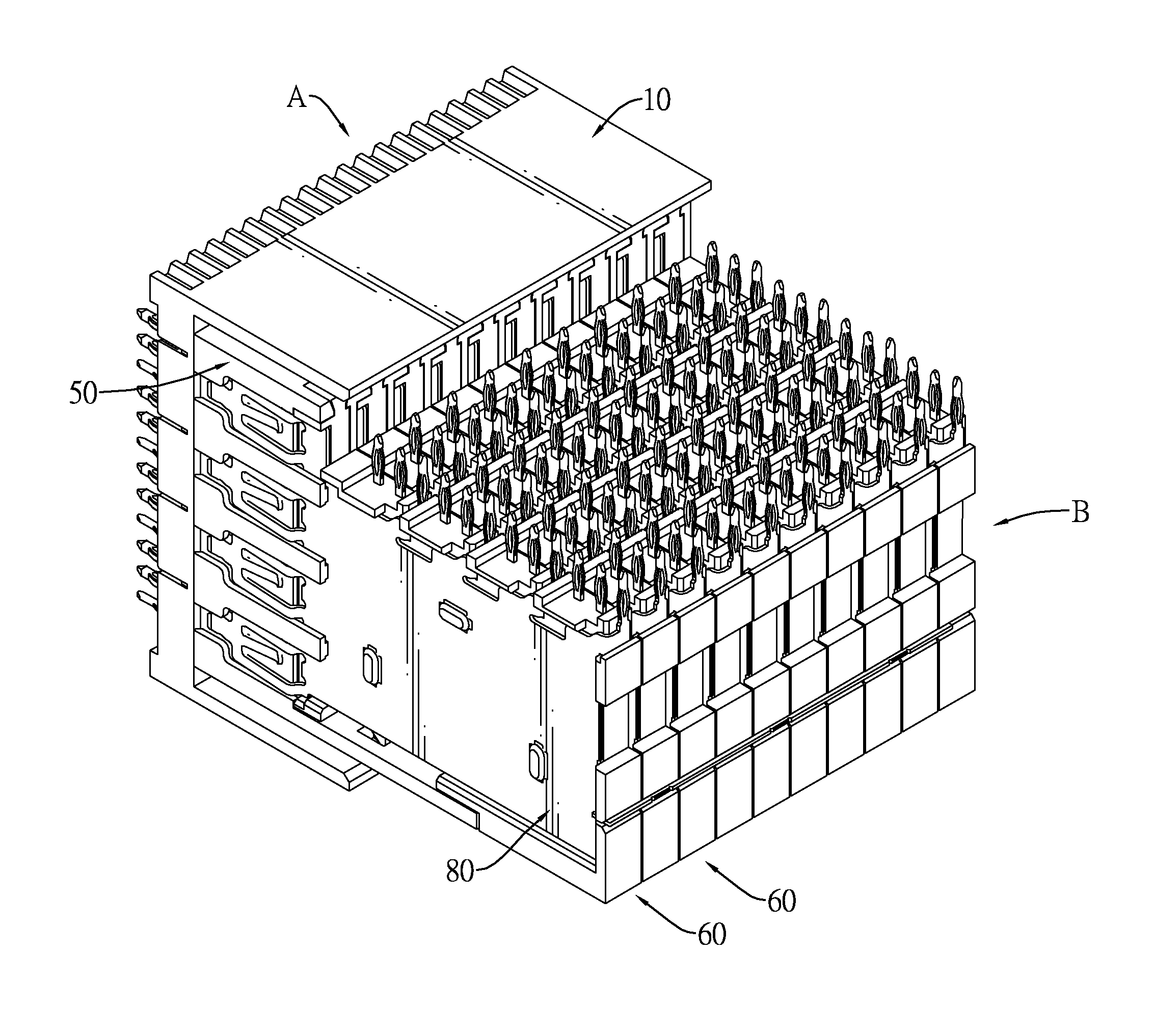
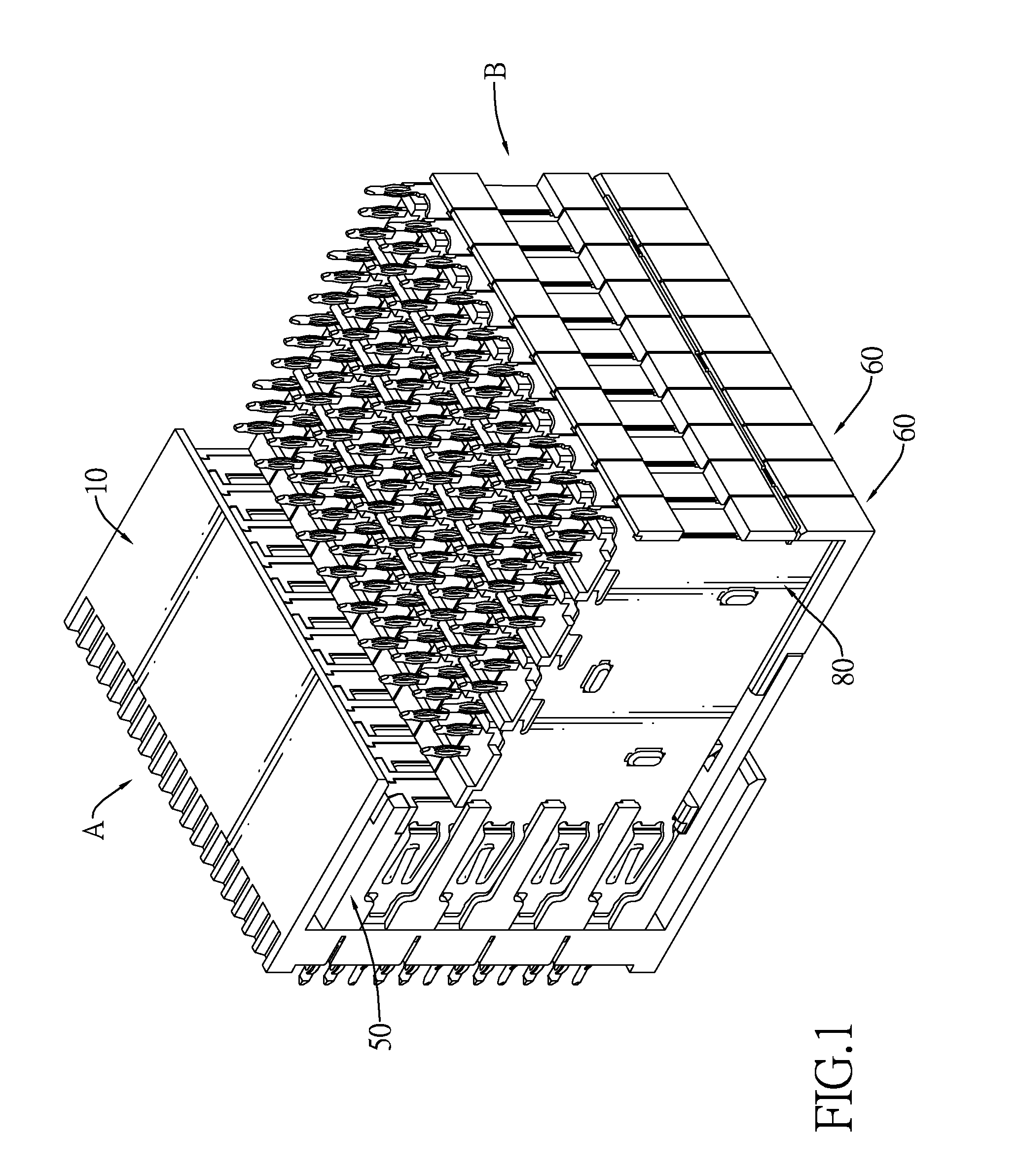
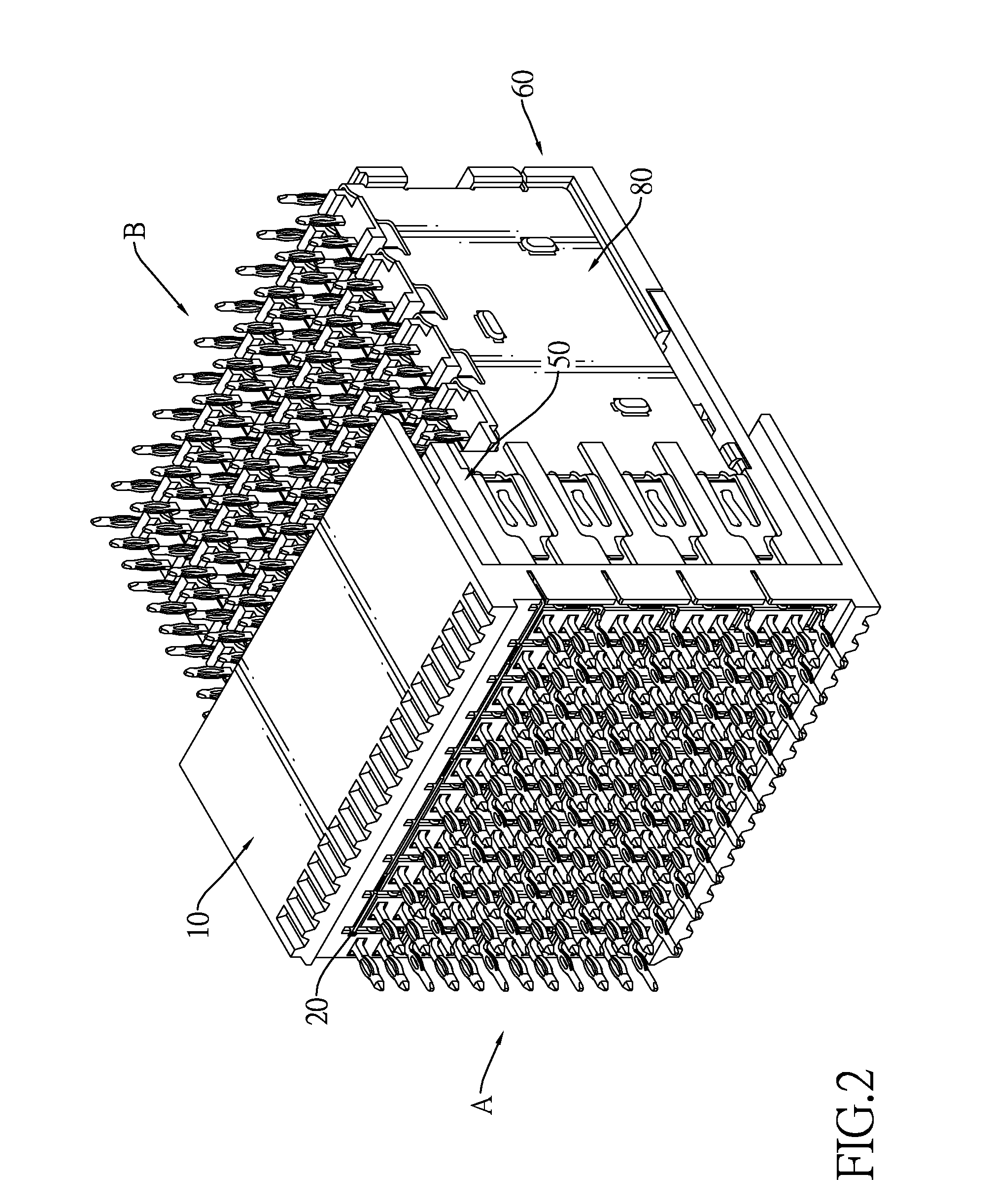
[0028]With reference to FIGS. 1 to 6, a male connector A and a female connector B are mounted on different PCBs and detachably engage each other to electrically connect the PCBs.

[0029]With further reference to FIGS. 8 to 12, the male connector A comprises an insulating housing 10, multiple signal terminals 30, multiple grounding terminal modules 40 and a supporting crossbar 20.

[0030]The insulating housing 10 has a front, a rear, multiple signal terminal holes 13 and multiple grounding terminal holes 14. The signal terminal holes 13 are defined through the insulating housing 10. The grounding terminal holes 14 are defined through the insulating housing 10 and each grounding terminal hole 14 may have an L-shaped cross section and a slit 141 extending transversely from and communicating with the grounding terminal hole 14.

[0031]The signal terminals 30 are mounted respectively and longitudinally through and correspond to the signal terminal holes 13, extend out from the front of the ins...


PUM


Abstract

A male connector has an insulating housing, multiple signal terminals, and multiple grounding modules. The signal terminals are mounted through the insulating housing. The grounding terminal modules are mounted through the insulating housing. Each grounding terminal module is integrally formed into one piece and has multiple grounding terminals. Adjacent grounding terminals are connected integrally to each other so that the grounding terminals of each grounding terminal module are arranged in a line. The integrally formed ground terminal modules reduce a total tolerance of the grounding terminals and increase the production rate of the male connector.

Description

BACKGROUND OF THE INVENTION[0001]1. Field of the Invention[0002]The present invention relates to a connector, and more particularly to a male connector and a female connector corresponding to the male connector. The male connector has multiple sets of grounding terminals and the grounding terminals of each set are integrally formed together to reduce signal interference, decrease the assembling tolerance and improve quality of fabrication and production rate. The female connector is structurally firm to prevent inadvertent disassembly and improve signal transmission stability.[0003]2. Description of Related Art[0004]Printed circuit boards (PCB) are important members for holding electrical components such as chips, capacitors and resistors. To expand functions, some PCBs are connected to additional PCBs through connector assemblies. Such connector assembling for connecting different PCBs has a male connector and a female connector. The male connector is connected to a PCB while the f...

Claims


Application Information

Patent Timeline
Patent Type & Authority Patents(United States)
IPC IPC(8): H01R13/648
CPCH01R13/6587H01R12/716
Inventor LEE, KUO-CHINGMENG, TA-TEHGUAN, JIAN-LI
Owner ADVANCED CONNECTEK INC
Why Eureka
Try Eureka