Angular velocity sensor

a technology of angular velocity sensor and angular velocity, applied in the direction of acceleration measurement using interia force, turn-sensitive devices, instruments, etc., to achieve the effect of reducing servo voltage change and high detection accuracy

Active Publication Date: 2013-10-08
DENSO CORP
View PDF7 Cites 1 Cited by
  • Summary
  • Abstract
  • Description
  • Claims
  • Application Information

AI Technical Summary

Benefits of technology

[0010]In view of the foregoing problems, it is an object of the present invention to provide an angular velocity sensor that can restrict a decrease in a servo voltage change with respect to an angular velocity change due to machining error.
[0012]The angular velocity sensor can restrict a decrease in a servo voltage change with respect to an angular velocity change due to machining error. Thus, the angular velocity sensor can have a high detection accuracy.

Problems solved by technology

The angular velocity sensor can restrict a decrease in a servo voltage change with respect to an angular velocity change due to machining error.

Method used


Image

  • Angular velocity sensor
  • Angular velocity sensor
  • Angular velocity sensor

Examples


Embodiment Construction

[0019]An angular velocity sensor 100 according to an embodiment of the present invention will be described with reference to drawings.

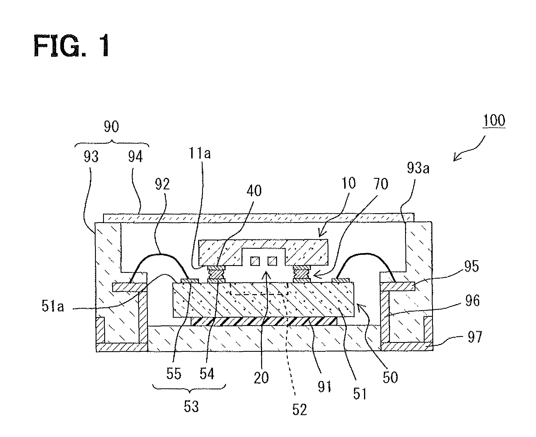
[0020]As shown in FIG. 1, the angular velocity sensor 100 includes a sensor chip 10, a circuit chip 50, a plurality of bumps 70, and a package 90. The sensor chip 10 and the circuit chip 50 are mechanically and electrically coupled with each other through the bumps 70. The circuit chip 50 and the package 90 are mechanically coupled with each other through an adhesive 91. The circuit chip 50 and the package 90 are electrically coupled with each other through wires 92. The sensor chip 10 and the circuit chip 50 are housed in a space defined by the package 90

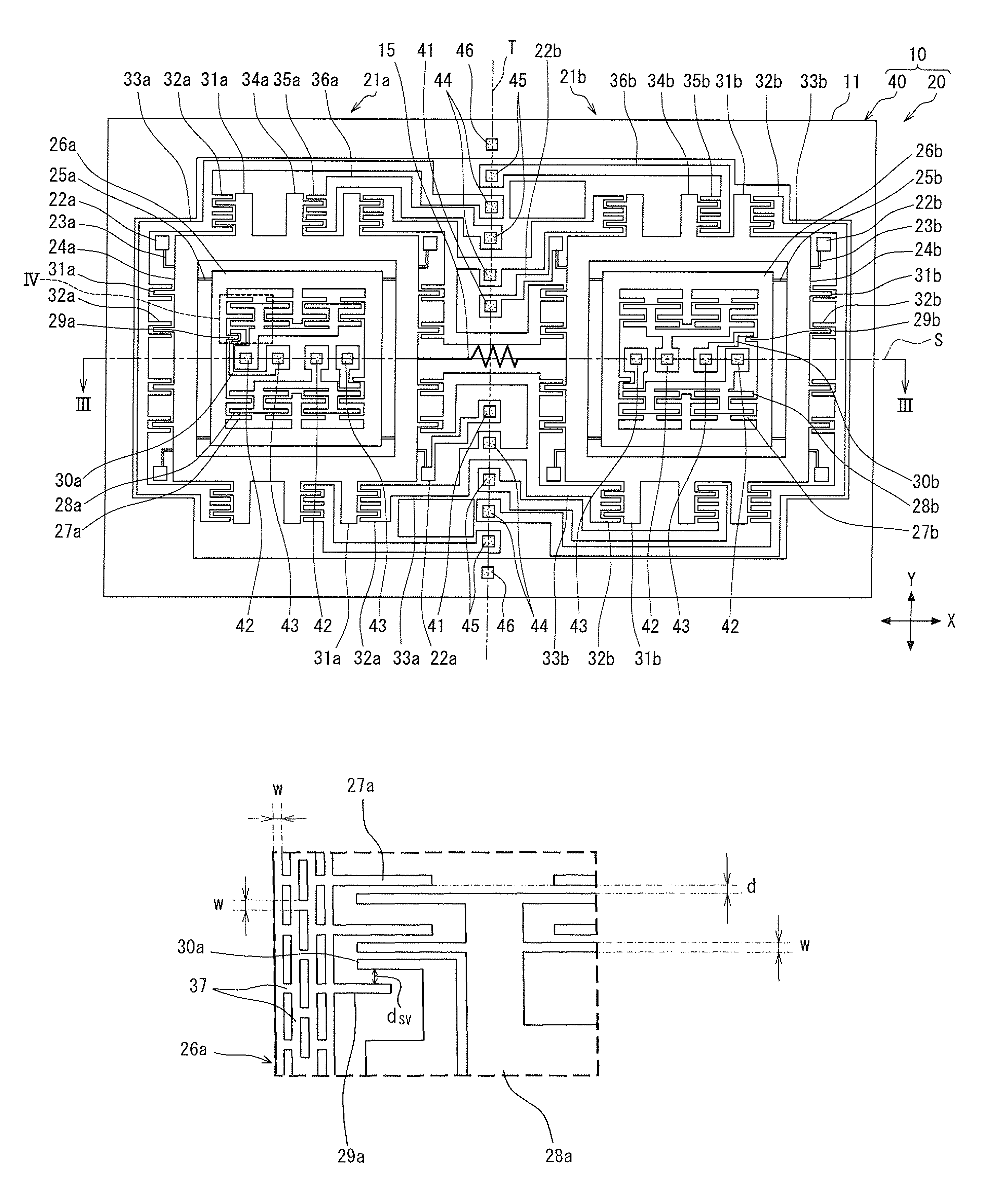
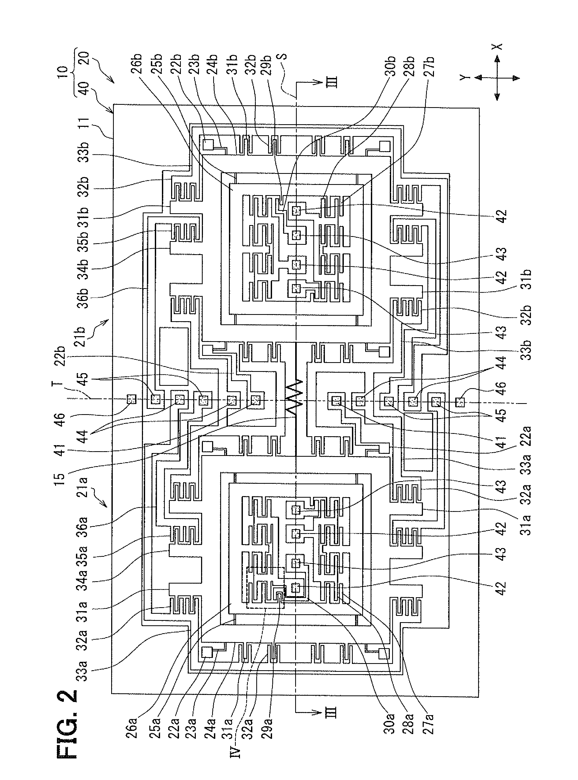
[0021]The sensor chip 10 includes the semiconductor substrate 11 having a front surface 11a. In the following description, a direction along the front surface 11a is referred to as an X-axis direction, a direction along the front surface 11a and perpendicular to the X-axis direction is referred to as...


PUM


Abstract

In an angular velocity sensor, a beam portion couples a pair of vibrators with each other and couples each of the vibrators to a substrate to enable the pair of vibrators to be movable in a first direction and a second direction that are perpendicular to each other. The driving portion vibrates the pair of vibrators in opposite phases in the first direction. The detecting portion detects displacement of the pair of vibrators in the second direction as a change in capacitance. The detecting portion includes first and second detecting electrodes. The restricting portion restricts displacement of the pair of vibrators in the second direction based on the change in capacitance. The restricting portion includes first and second restricting electrodes, and an electrode interval between the restricting electrodes is twice a width of the detecting electrodes in the second direction.

Description

CROSS REFERENCE TO RELATED APPLICATIONS[0001]The present application is based on and claims priority to Japanese Patent Application No. 2010-108605 filed on May 10, 2010, the contents of which are incorporated in their entirety herein by reference.BACKGROUND OF THE INVENTION[0002]1. Field of the Invention[0003]The present invention relates to an angular velocity sensor.[0004]2. Description of the Related Art[0005]Japanese Patent No. 3,606,164 (corresponding to U.S. Pat. No. 6,473,290, referred to as the patent document 1 hereafter) discloses an angular velocity sensor that includes a substrate, a movable unit coupled with the substrate through a supporting beam, a comb-shaped movable electrode provided in the movable unit, and a comb-shaped fixed electrode provided in the substrate. The movable unit is movable in a detecting direction due to the supporting beam. The comb-shaped fixed electrode includes a plurality of fixed electrode units arranged in the second direction at predeter...

Claims


Application Information

Patent Timeline
Patent Type & Authority Patents(United States)
IPC IPC(8): G01C19/56G01C19/574G01C19/5747
CPCG01C19/5747
Inventor SAKAI, MINEKAZUAO, KENICHI
Owner DENSO CORP
Why Eureka
Try Eureka