Virtual image display device

a display device and virtual image technology, applied in the field of virtual image display devices, can solve the problems of not necessarily perfectly see-through, difficult to make an effective pupil diameter, and difficult to make a large display size of virtual images, and achieve the effects of low absorbance, low transmittance sensitivity, and high efficiency

Active Publication Date: 2013-10-22
SEIKO EPSON CORP
View PDF15 Cites 258 Cited by
  • Summary
  • Abstract
  • Description
  • Claims
  • Application Information

AI Technical Summary

Benefits of technology

[0009]An advantage of some aspects of the invention is to provide a virtual image display device that can make a display size of a virtual image large with a simple configuration, can secure a large Eyring diameter, and thereby can realize a preferable see-through observation.

Problems solved by technology

However, in the device disclosed in JP-A-2006-3879 or the like, the see-through state is realized by a pupil division method that uses a light guiding optical system in which an emission opening is smaller than a pupil size, such that it is difficult to make a display size of the virtual image large.
In addition, a light guiding optical system that is smaller than the size of the pupil is used, such that it is difficult to make an effective pupil diameter (a lighting diameter that allows the virtual image to be taken in, and is called an Eyring diameter) large so as to correspond to an individual pupil width in humans.
In addition, the emission opening or a casing of the light guiding optical system is physically disposed in the vicinity of the pupil, such that a blind spot is generated, and therefore it is not necessarily perfectly see-through.
In this case, it is necessary to display a center image and left and right images, which make up the entire image while they are changed at a time interval by one liquid crystal panel, such that a virtual image display device becomes complex and an observed image becomes dark.

Method used


Image

  • Virtual image display device
  • Virtual image display device
  • Virtual image display device

Examples


Embodiment Construction

[0038]Hereinafter, a virtual image display device related to an embodiment of the invention will be described in detail with reference to the accompanying drawings.

A. External Appearance of Virtual Image Display Device

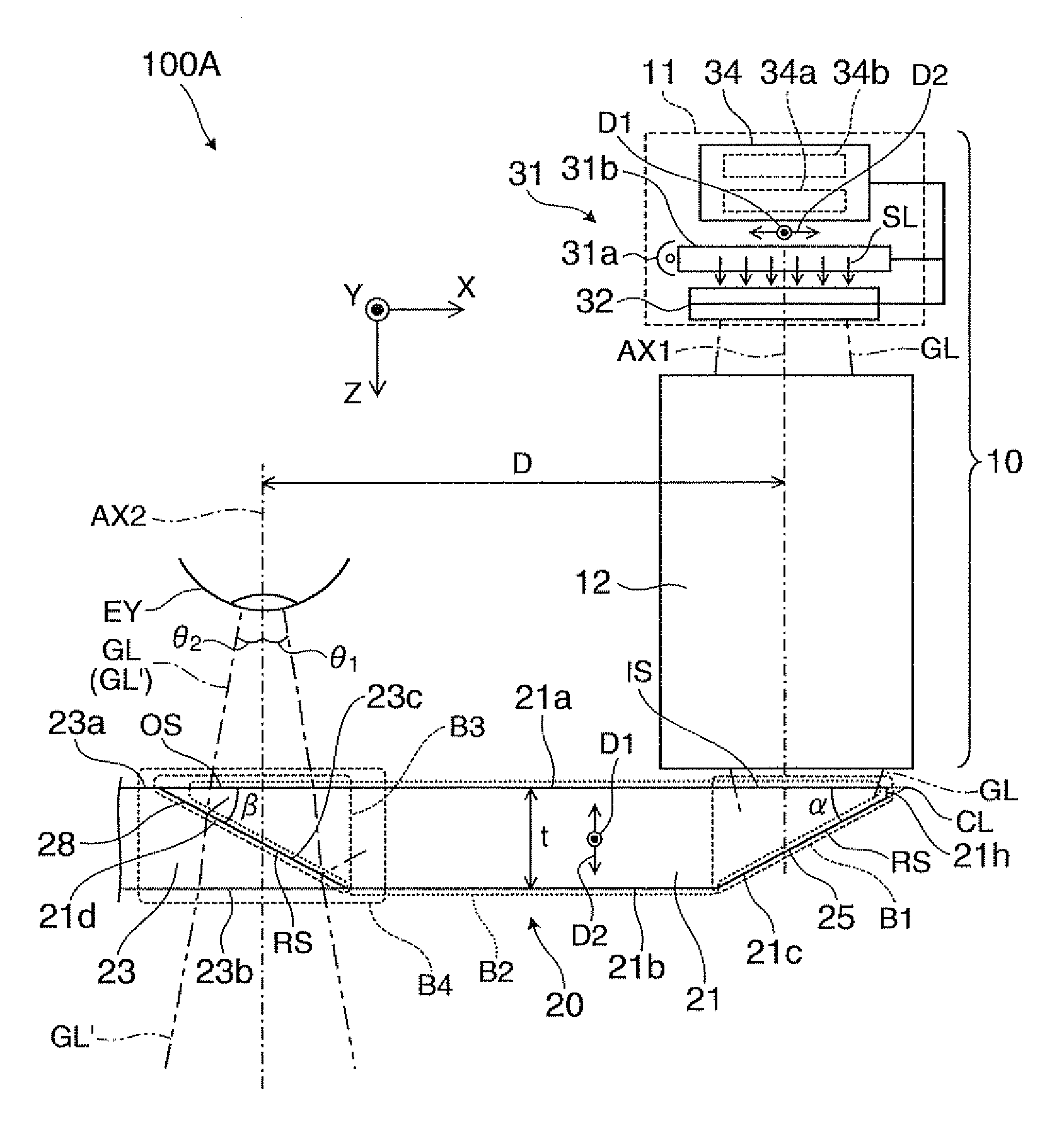
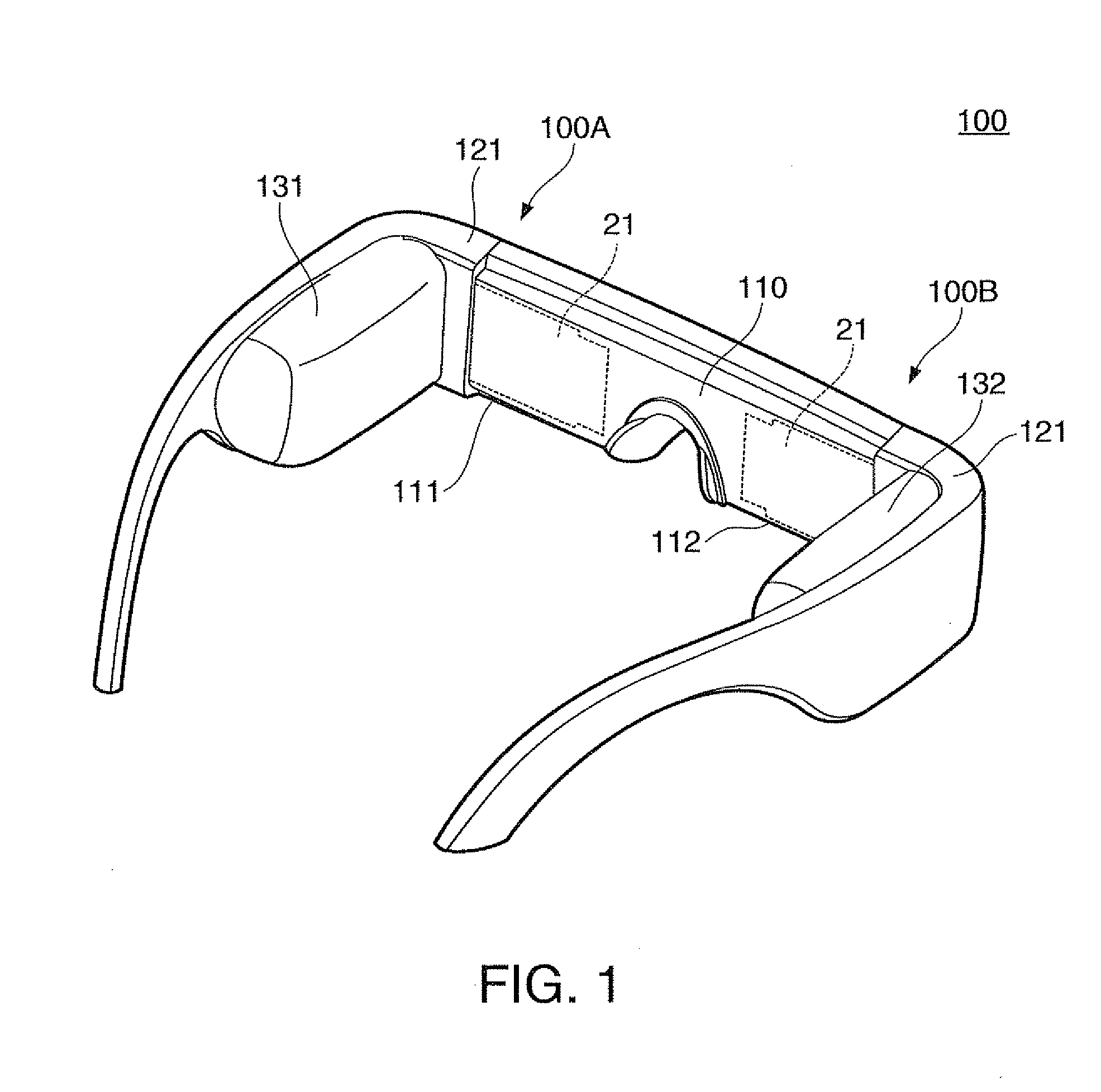
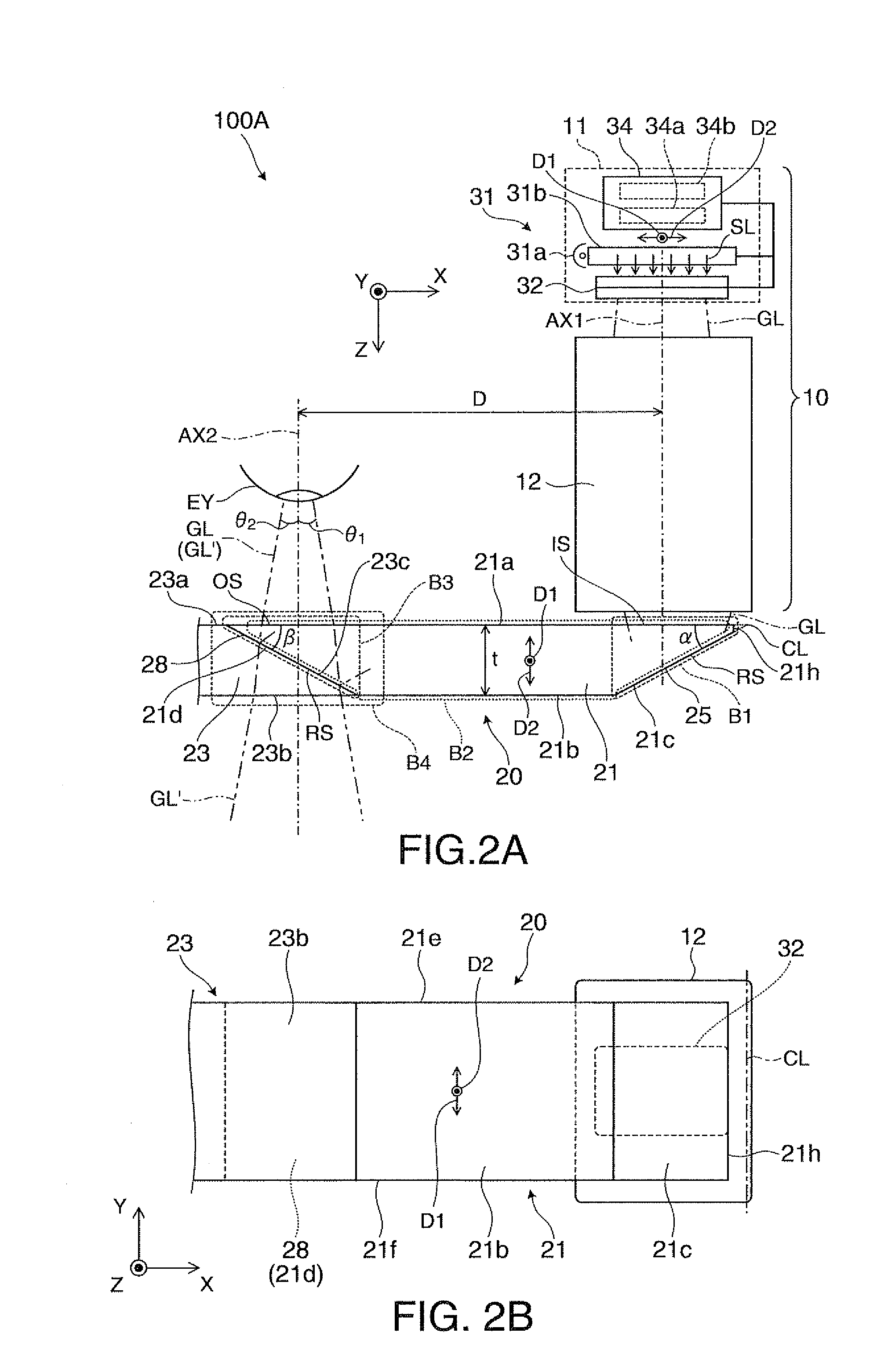
[0039]A virtual image display device 100 of an embodiment illustrated in FIG. 1 is a head-mounted display having the same external appearance as eyeglasses, and allows an observer wearing this virtual image display device 100 to perceive image light via a virtual image and allows the observer to observe an external image in a see-through manner. The virtual image display device 100 includes an optical panel 110 that covers the front of the observer's eyes, a frame 121 that maintains the optical panel 110, and first and second driving portions 131 and 132 that are provided at a portion ranging from end-piece to temple of the frame 121. Here, the optical panel 110 includes a first panel portion 111 and a second panel portion 112, and both panel portions 111 and 112 are f...


PUM


Abstract

Image light reflected by a third reflective surface of a light incidence portion is propagated while being totally reflected by first and second reflective surfaces of a light guiding portion, is reflected by a fourth reflective surface of a light emission portion, and is incident to observer's eye as a virtual image. At this time, the number of times of reflection of first image light, which is emitted from a first partial region of an image display device, in the light guiding portion, and the number of times of reflection of second image light, which is emitted from a second partial region of the image display device in the light guiding portion are different from each other, such that it is possible to take in the image light beams from the different partial regions of the image display device with a relatively wide angle of view.

Description

[0001]This Application claims priority to JP 2011-022442 filed in Japan on Feb. 4, 2011, the entire disclosure of which is herein incorporated by reference in its entirety.BACKGROUND[0002]1. Technical Field[0003]The present invention relates to a virtual image display device such as a head-mounted display that is used by being mounted on the head.[0004]2. Related Art[0005]In recent years, as a virtual image display device that allows a virtual image to be formed and to be observed similarly to the head-mounted display, various virtual image display devices of a type in which image light from a display element is guided to a pupil of an observer by a light guiding plate have been suggested.[0006]In this virtual image display device, in order that the image light and external light overlap each other, a see-through optical system has been suggested (refer to JP-A-2006-3879 and JP-A-2010-224473).[0007]However, in the device disclosed in JP-A-2006-3879 or the like, the see-through state...

Claims


Application Information

Patent Timeline
Patent Type & Authority Patents(United States)
IPC IPC(8): G02B27/14G02B27/01
CPCG02B27/0172G02B2027/0125G02B2027/0178G02B6/0045
Inventor TOTANI, TAKAHIROTAKAGI, MASAYUKIMIYAO, TOSHIAKIKOMATSU, AKIRATAKEDA, TAKASHI
Owner SEIKO EPSON CORP
Why Eureka
Try Eureka