Operating mechanism for a parking brake

a technology of operating mechanism and parking brake, which is applied in the direction of mechanical control devices, controlling members, limiting/preventing/returning parts movement, etc., can solve the problems of increasing the installation time and complicating the installation

Inactive Publication Date: 2014-03-11
DIETZ AUTOMOTIVE
View PDF51 Cites 0 Cited by
  • Summary
  • Abstract
  • Description
  • Claims
  • Application Information

AI Technical Summary

Benefits of technology

[0007]It is an object of the present invention to reduce the installation expenditure for an operating mechanism of the aforementioned type.
[0010]An advantage of the operating mechanism according to the invention is that two separate operational steps are no longer required for the assembly of the locking device, the fixation of the detent and the installation of the spring element on the manual brake lever. Rather, owing to the fact that the connecting element and the spring element form a single structural unit, the detent and simultaneously also the spring element can be installed during a single operational step on the manual brake lever, thereby resulting in a considerable savings in time during the assembly of the manual brake lever.
[0011]It is furthermore advantageous that the structural unit, including a connecting element and spring element, can be produced easily and quickly, preferably by simply and easily fitting the spring element onto the connecting element. Since the structural unit can be assembled outside of the manual brake lever, essentially no restrictions exist which are caused by the manual brake lever design. It is particularly advantageous that no adjustment of the spring element relative to the connecting element is necessary to form the structural unit.
[0013]The assembly of the detent and the attaching of the spring element on the detent are thus made even easier since the access to the bore is not blocked by additional parts of the manual brake lever.
[0018]It is thus possible to obtain a pivot bearing for the detent in a simple manner, wherein this type of design furthermore permits an installation of the pivot bearing which can be realized even with untrained personnel.

Problems solved by technology

With known operating mechanisms, the installation of the locking device is relatively time-consuming.
Since the installation of the spring element must be realized with a fully-installed manual brake lever and thereon positioned detent, typically very little clearance space is available for inserting the spring element, which further complicates the installation.

Method used


Image

  • Operating mechanism for a parking brake
  • Operating mechanism for a parking brake
  • Operating mechanism for a parking brake

Examples


Embodiment Construction

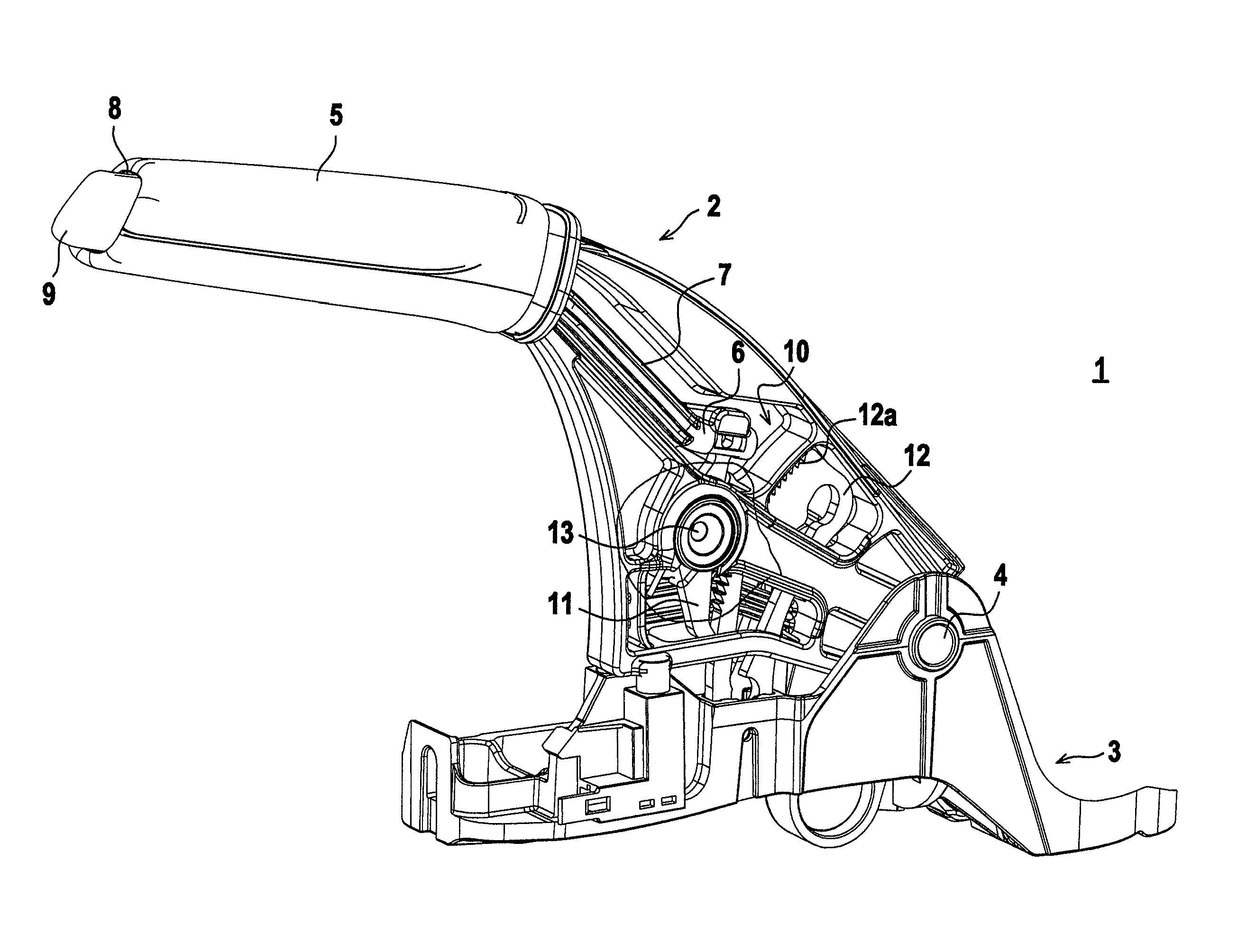
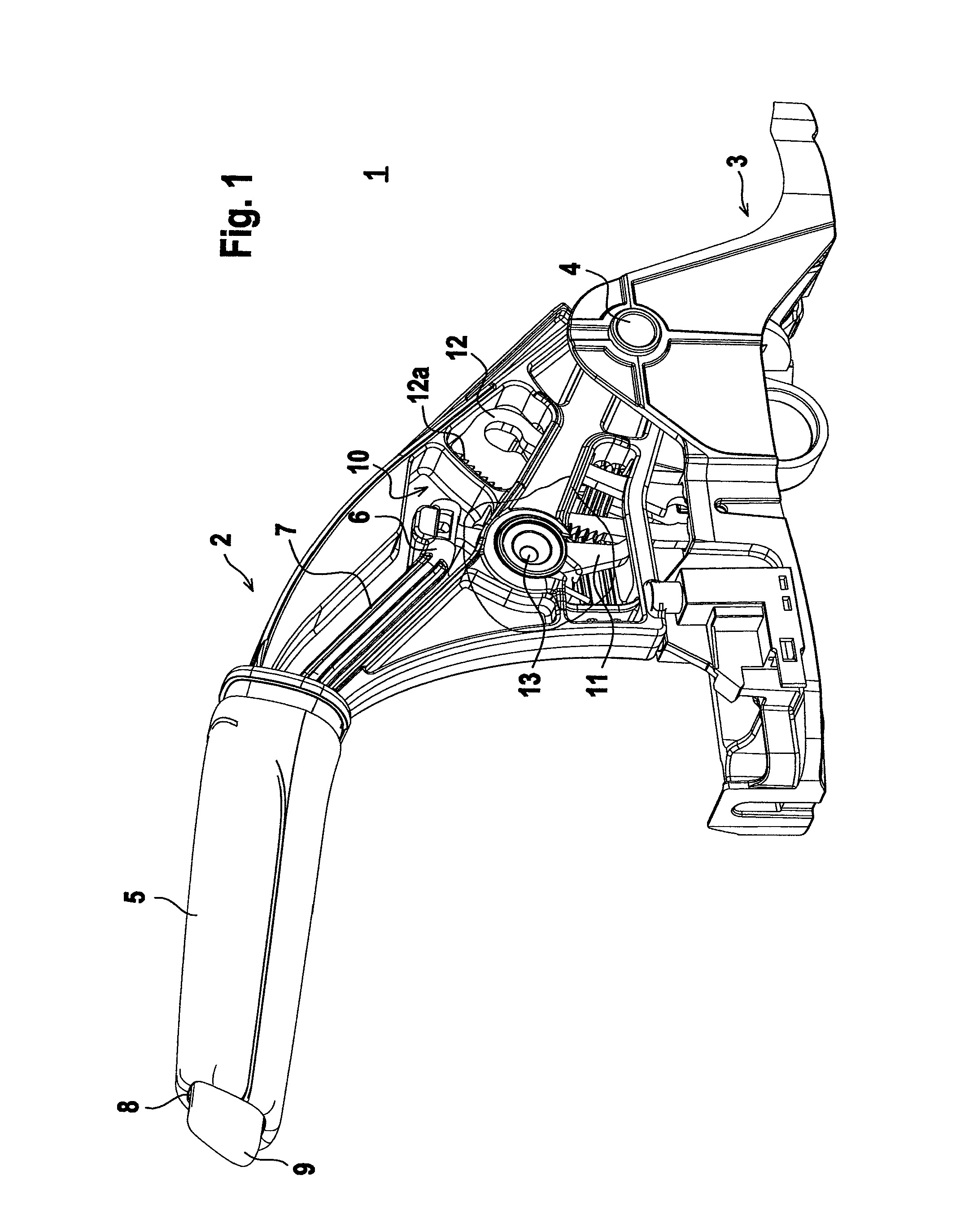
[0025]FIG. 1 shows an exemplary embodiment of an operating mechanism 1 for a parking brake in a vehicle.

[0026]The operating mechanism 1 comprises a manual brake lever 2 that can pivot around a horizontal axis on a bearing block 3, using a bearing journal 4. The manual brake lever 2 includes a basic body, having a front end that is embodied as a tubular housing. A handle 5 is positioned on this tubular housing.

[0027]The respective position of the manual brake lever 2 is transmitted via a sheathed cable, not shown herein, to the parking brake which is also not shown herein.

[0028]An activation rod 6, in the present case comprising an injection-molded plastic part, is positioned in the manual brake lever 2. The activation rod 6 is guided inside a cavity 7 of the manual brake lever 2. The activation rod 6 projects from the front end of the tubular housing. A push button 9 is mounted in this front end of the activation rod 6, in an opening 8 of the grip 5. The push button 9 can be depress...


PUM


Abstract

An operating mechanism for a parking brake includes a manual brake lever pivotably coupled to a bearing block and a locking device adapted to lock the manual brake lever into a position. The locking device includes a detent arranged on the manual brake lever and adapted to pivot around a pivoting axis, the detent having a bore, a locking segment connected to the bearing block, a spring element adapted to hold the detent into a locking position on the locking segment, and a connecting element adapted to secure the detent on the manual brake lever. The connecting element and the spring element jointly form a single structural unit adapted for insertion into the bore in the detent during installation of the detent on the manual brake lever.

Description

CROSS-REFERENCE TO RELATED APPLICATION[0001]This application claims priority under 35 U.S.C. §119 to German Patent Application No. 20 2009 008 792.1, filed in Germany on Jun. 26, 2009, the entire subject matter of which is expressly incorporated herein by reference.BACKGROUND OF THE INVENTION[0002]The invention relates to an operating mechanism for a parking brake.[0003]An operating mechanism for a parking brake is known from German Document DE 195 21 159 C2. This operating mechanism comprises a manual brake lever which is positioned so as to pivot on a bearing block. A single activation rod is provided for operating the parking brake, wherein this activation rod engages in a locking device. The activation rod extends inside a tubular housing for the manual brake lever. A push button is provided on the front end of the activation rod which projects outside the tubular housing and can thus be operated by a user.[0004]The locking device includes a locking segment and a detent. The loc...

Claims


Application Information

Patent Timeline
Patent Type & Authority Patents(United States)
IPC IPC(8): B60T7/10
CPCB60T7/105Y10T74/20696Y10T74/20396Y10T74/20684
Inventor BARCIN, BARIS
Owner DIETZ AUTOMOTIVE
Why Eureka
Try Eureka