Separator tool with indexing head

a technology of indexing tool head and separater, which is applied in the direction of metal-working hand tools, work holders, lifting devices, etc., can solve the problems of inadvertent damage, less sturdy, and slender tool handles configured for pneumatic drivers

Active Publication Date: 2014-07-01
APEX BRANDS
View PDF10 Cites 15 Cited by
  • Summary
  • Abstract
  • Description
  • Claims
  • Application Information

AI Technical Summary

Problems solved by technology

Typically, the tool handles configured for use with pneumatic drivers are more slender, and therefore less sturdy, than the handles that are configured to be struck manually by the user.
As such, although it is possible to strike these handles, it is not desirable in that they can be inadvertently damaged.
Even so, as automobile engines have become more complicated in recent years, and excess space more limited within the engine compartment, it is not uncommon for the overall length of the separating tool, dictated primarily by the length of the handle, to prevent a user from having adequate space in which to manually strike the distal end of the handle or attach a pneumatic driver.

Method used


Image

  • Separator tool with indexing head
  • Separator tool with indexing head
  • Separator tool with indexing head

Examples


Embodiment Construction

[0020]Reference will now be made in detail to presently preferred embodiments of the invention, one or more examples of which are illustrated in the accompanying drawings. Each example is provided by way of explanation, not limitation, of the invention. In fact, it will be apparent to those skilled in the art that modifications and variations can be made in the present invention without departing from the scope and spirit thereof. For instance, features illustrated or described as part of one embodiment may be used on another embodiment to yield a still further embodiment. Thus, it is intended that the present invention covers such modifications and variations as come within the scope of the appended claims and their equivalents.

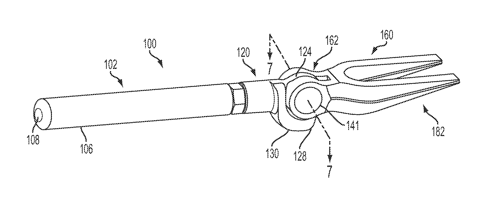
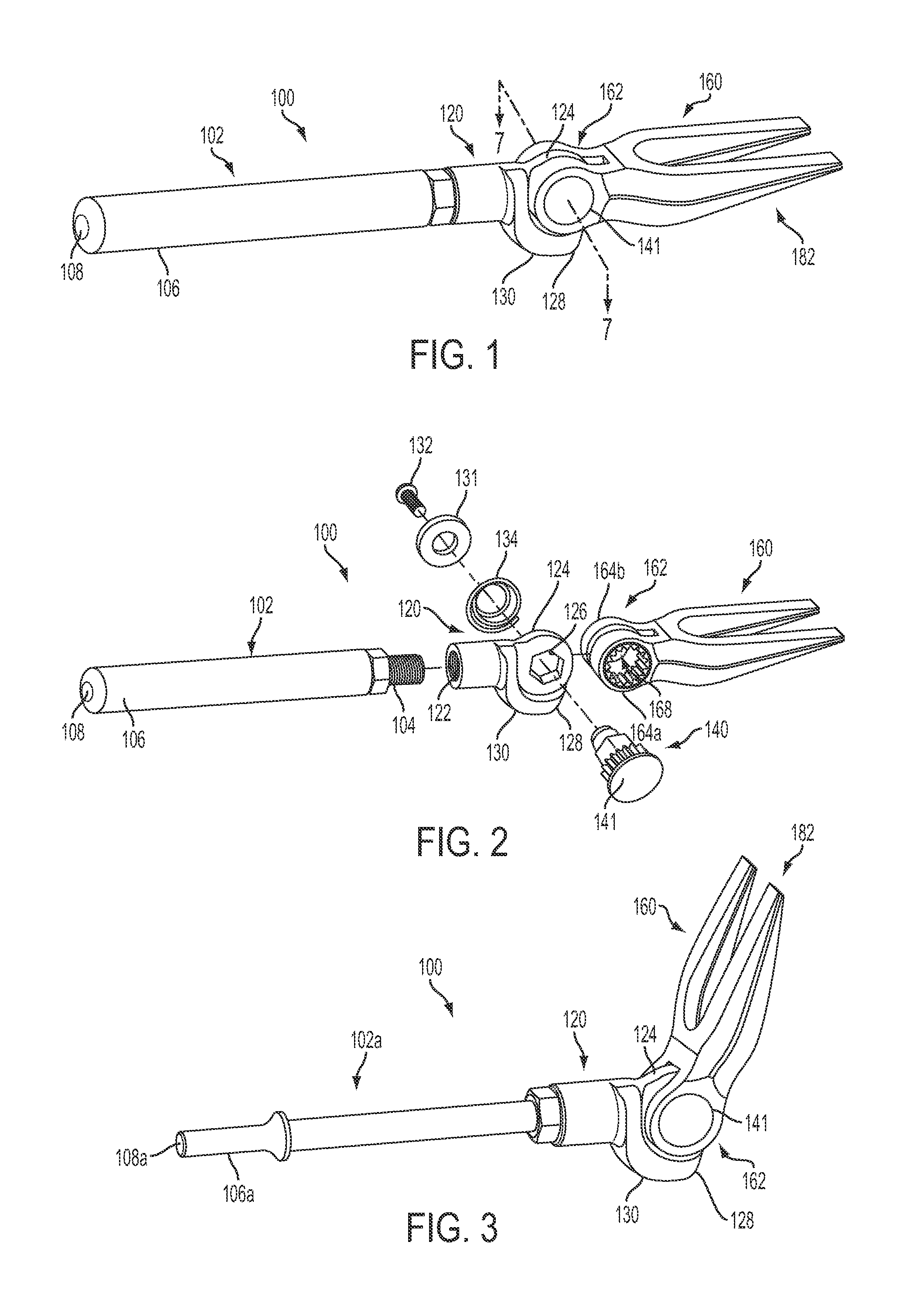
[0021]Referring to FIGS. 1 and 2, a separator tool 100 in accordance with the present invention includes a tool head 160 pivotably mounted to a handle 102 such that the angle of tool head 160 relative to the longitudinal center axis of handle 102 may be sele...


PUM


Abstract

A separator tool including a handle formed a hub at a first end, the hub defining a through bore that is transverse to a longitudinal center axis of the handle, a tool head formed with an integral yoke including opposed first and second legs, the tool head being pivotably coupled to the first end of the handle, an indexing stud slidably disposed within the through bores of the hub and first and second legs of the yoke, and the indexing stud being slidable within the through bores between a first position in which the tool head is secured in a fixed position relative to the handle, and a second position in which the tool head is pivotable relative to the handle.

Description

FIELD OF THE INVENTION[0001]The present invention relates generally to a tool for use in vehicle repairs. More particularly, the present invention relates to a separator tool including an indexing tool head.BACKGROUND OF THE INVENTION[0002]Tools used for separating components when performing automobile repairs are well known. A typical separating tool may include a wedge-shaped head disposed at a first end of an elongated handle configured to be impacted by another tool, such as a hammer or maul. The wedge-shaped head typically includes a pair of spaced apart, tapered prongs, with the tapered ends configured to be urged between the components to be separated. For example, separator tools are frequently used to separate components, such as tie rod ends and ball joints, from vehicle steering systems. For ease of description, only removal of tie rod ends is addressed here. More specifically, in use, the tapered ends of the prongs are positioned between a tie rod end and the correspondi...

Claims


Application Information

Patent Timeline
Patent Type & Authority Patents(United States)
IPC IPC(8): B25B11/00
CPCB25B27/02
Inventor BRUCE, MICHAELGHARIB, AWAD ALY
Owner APEX BRANDS
Why Eureka
Try Eureka