Rope termination

a technology of rope and sleeve, which is applied in the direction of ropes and cables for vehicles/pulleys, swivels, applications, etc., can solve the problems of unprotected fibres, unsuitable for providing a termination, and distorted fibres at both ends of the sleeve, so as to reduce the possibility of unbalanced moments, reduce the risk of rope failure, and maximize the tensile strength of the connection

Active Publication Date: 2014-07-22
OFFSPRING INT +1
View PDF19 Cites 0 Cited by
  • Summary
  • Abstract
  • Description
  • Claims
  • Application Information

AI Technical Summary

Benefits of technology

[0013]This arrangement offers a means for connecting a multi-core rope comprising a plurality of sub-ropes to load pins of a termination that overcomes that above mentioned problems associated with the prior art. In particular, the arrangement of sub-ropes on the load pins minimises compression and abrasion of the constituent fibre elements of the rope thereby reducing the risk of rope failure. By splicing individual sub-ropes as opposed to the whole rope itself, the size of the termination piece can be kept to a minimum.
[0037]It is preferable that the load pin is connected to sub-ropes of equal length so that tension is equally transferred between said load pin and each sub-rope. As described above, with reference to the first aspect of the present invention, this arrangement maximises the tensile strength of the connection, reduces the possibility of unbalanced moments and ultimately reduces the risk of rope failure.

Problems solved by technology

Although the Hood termination meets this need, it would not be suitable for providing a termination of a multi-core synthetic rope that would be able to withstand the typical loads encountered in the oil and gas industries.
However, the fibres are exposed to the environment and are not protected.
Also, while the ends of the sleeve over which the fibres are bent are curved, nevertheless, the fibres are distorted at both ends of the sleeve.

Method used


Image

  • Rope termination
  • Rope termination
  • Rope termination

Examples


Embodiment Construction

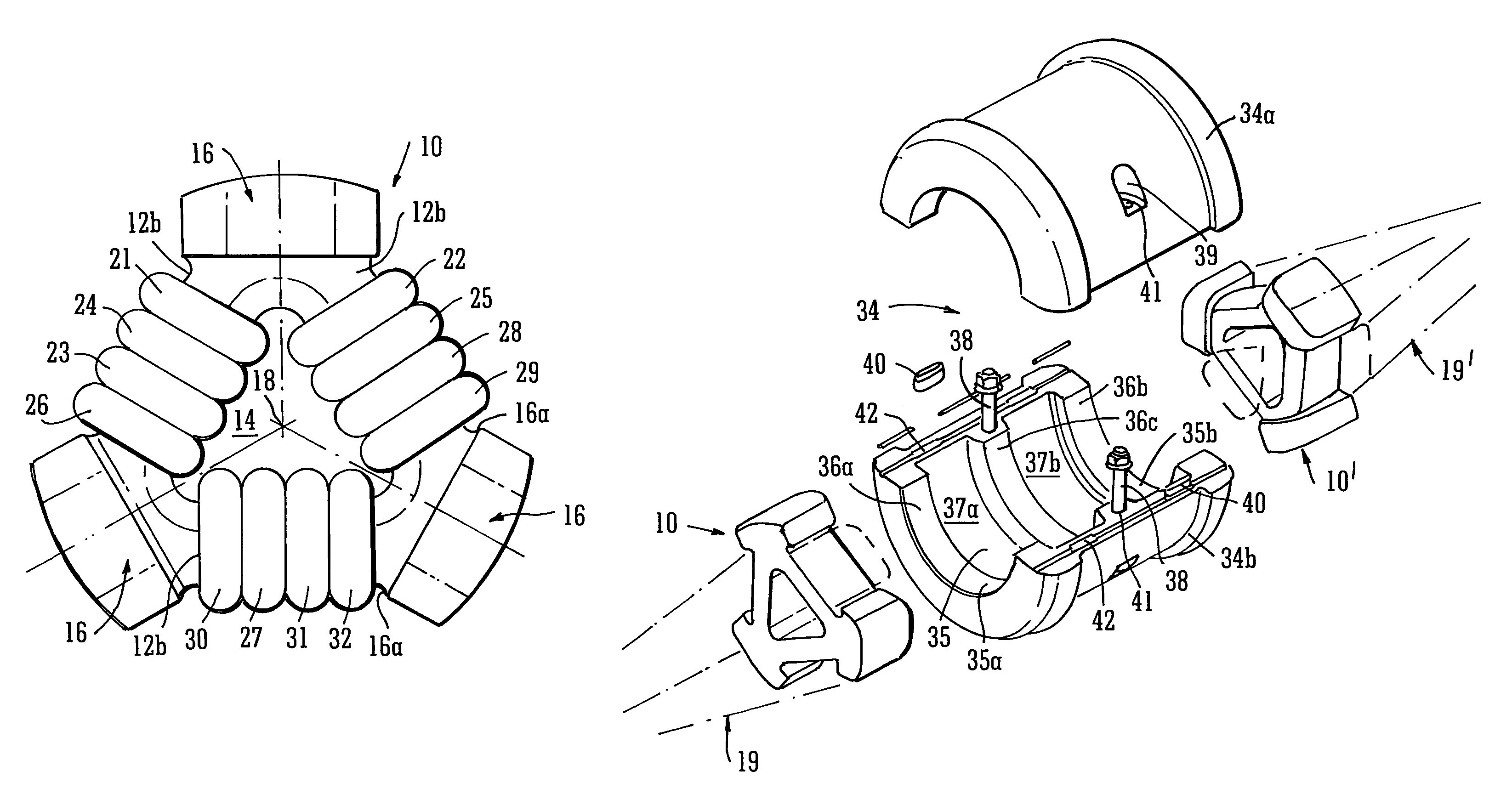
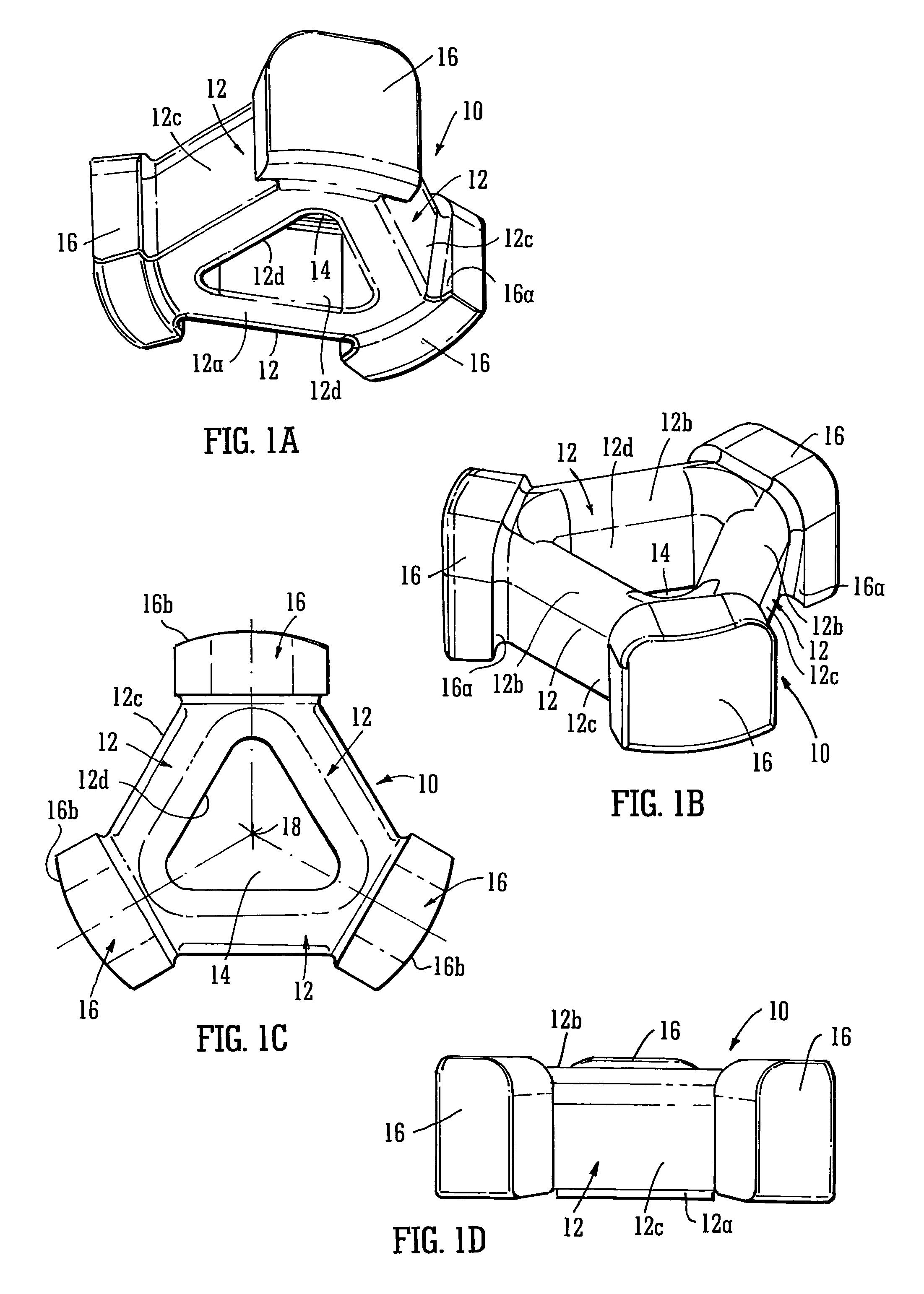
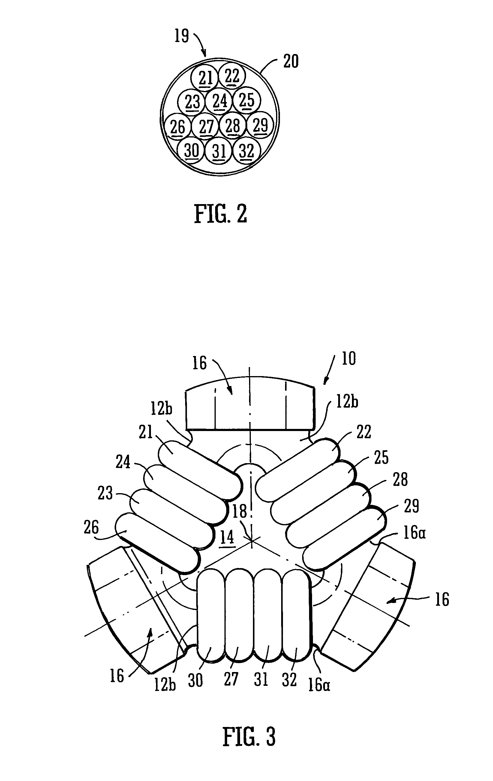
[0052]FIGS. 1A to 1D show an exemplary embodiment of a rope termination 10 according to the present invention. The rope termination 10 is for attachment to the end of a multi-core rope so that the rope may be anchored or connected to further similar multi-core ropes via a suitable rope connection assembly. As shown in the figures, the rope termination 10 comprises several load pins 12 arranged to form a closed shape around a central opening 14. In the particular embodiment shown in the figures, three identical load pins 12 are arranged in a triangular formation, however in alternative embodiments, any number of load pins 12 may be arranged into a closed shape. In particular, the closed shape may be a circle or any polygon. Since the load pins 12 of the rope termination 10 form a closed shape with a central opening 14, the rope termination 10 may be referred to as a “donut”.

[0053]Returning to the particular embodiment shown in the figures, each apex of the triangular shape has a radi...


PUM


Abstract

A rope termination (10) for a rope (19) having a plurality of sub-ropes (21 -32), the rope termination including a connection device having a load pin (12)wherein each of the plurality of sub-ropes (21 -32) is spliced into itself to form a looped end, wherein the looped ends are arranged on the load pin and each of the plurality of sub-ropes (21 -32) is of equal length. The connection device further includes a connector (34) for a rope connection assembly whereby tension is equally transferred between the load pin and each of the plurality of sub-ropes.

Description

CROSS-REFERENCE TO RELATED APPLICATIONS[0001]This application is a national stage application under 35 U.S.C. §371 of International Application No. PCT / GB2010 / 050647, titled ROPE TERMINATION, filed Apr. 21, 2010, which claims priority to Great Britain Patent Application No. 0907416.2, filed Apr. 30, 2009, both of which are hereby incorporated by reference in their entireties.[0002]This invention relates to rope terminations, and more particularly to rope terminations for ropes having a plurality of sub-ropes.BACKGROUND[0003]Synthetic multi-core ropes are used in a wide variety of fields, but are being increasingly used in the oil and gas industries, due to their strength and versatility. Amongst other tethering applications, multi-core ropes are used in the oil and gas industries to moor offshore facilities and anchor lines to the sea bed.[0004]Multi-core ropes can be made to withstand very heavy loads before breaking, in some cases supporting many thousands of tonnes. The strength ...

Claims


Application Information

Patent Timeline
Patent Type & Authority Patents(United States)
IPC IPC(8): F16G11/00F16G15/08
CPCF16G11/00F16G15/08Y10T403/4908Y10T24/3909Y10T24/3907F16G11/046F16G11/08
Inventor THOI, HONG TRIROWLEY, DAVID STUART
Owner OFFSPRING INT
Why Eureka
Try Eureka