Rope termination

Active Publication Date: 2012-02-16
OFFSPRING INT +1
View PDF14 Cites 4 Cited by
  • Summary
  • Abstract
  • Description
  • Claims
  • Application Information

AI Technical Summary

Benefits of technology

[0036]It is preferable that the load pin is connected to sub-ropes of equal length so that tension is equally transferred between said load pin and each sub-rope. As described above, with reference to t

Problems solved by technology

Although the Hood termination meets this need, it would not be suitable for providing a termination of a multi-core synthetic rope that would be able to withstand the typical loads encountered in the oil and gas industri

Method used


Image

  • Rope termination
  • Rope termination
  • Rope termination

Examples


Embodiment Construction

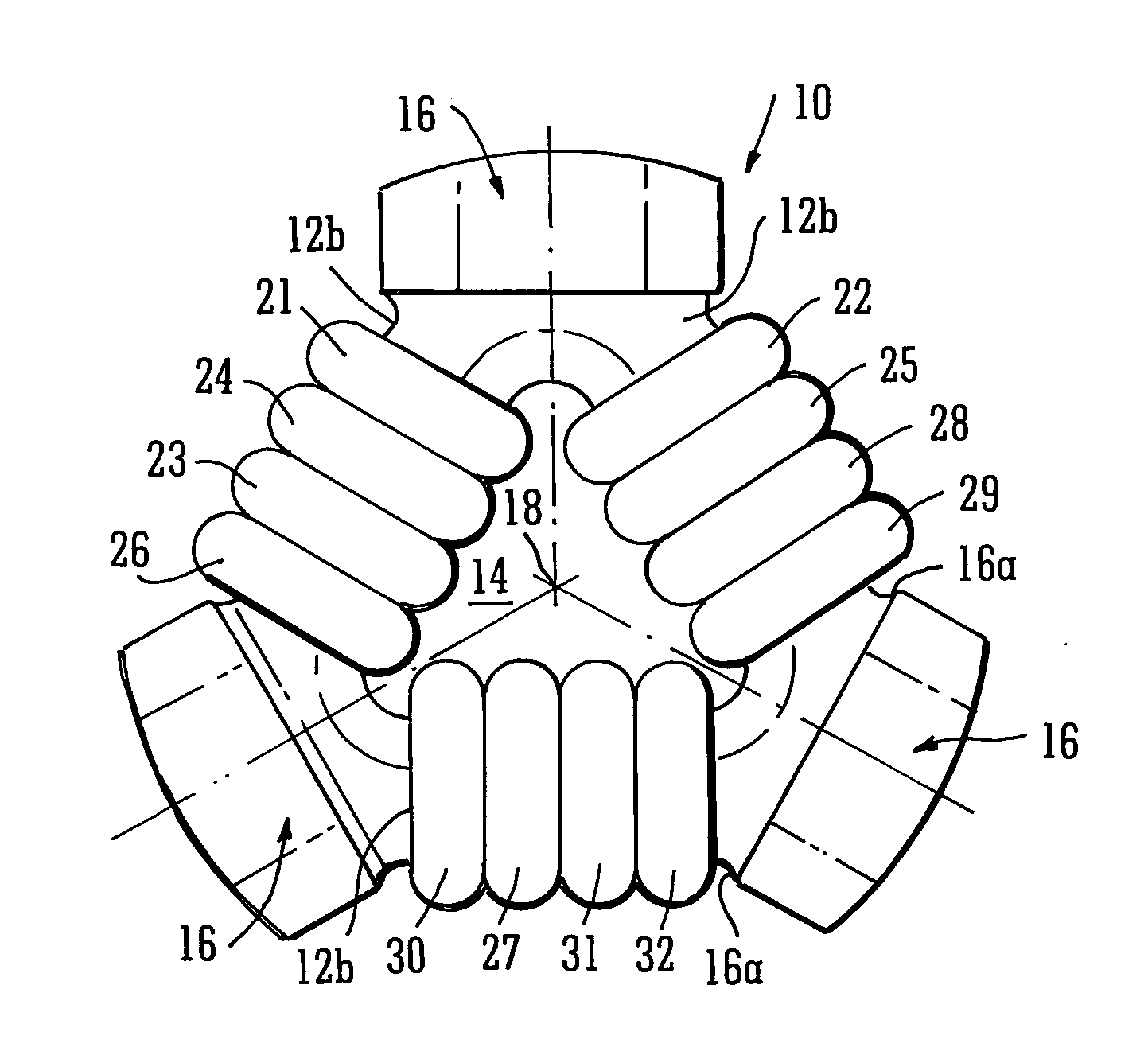
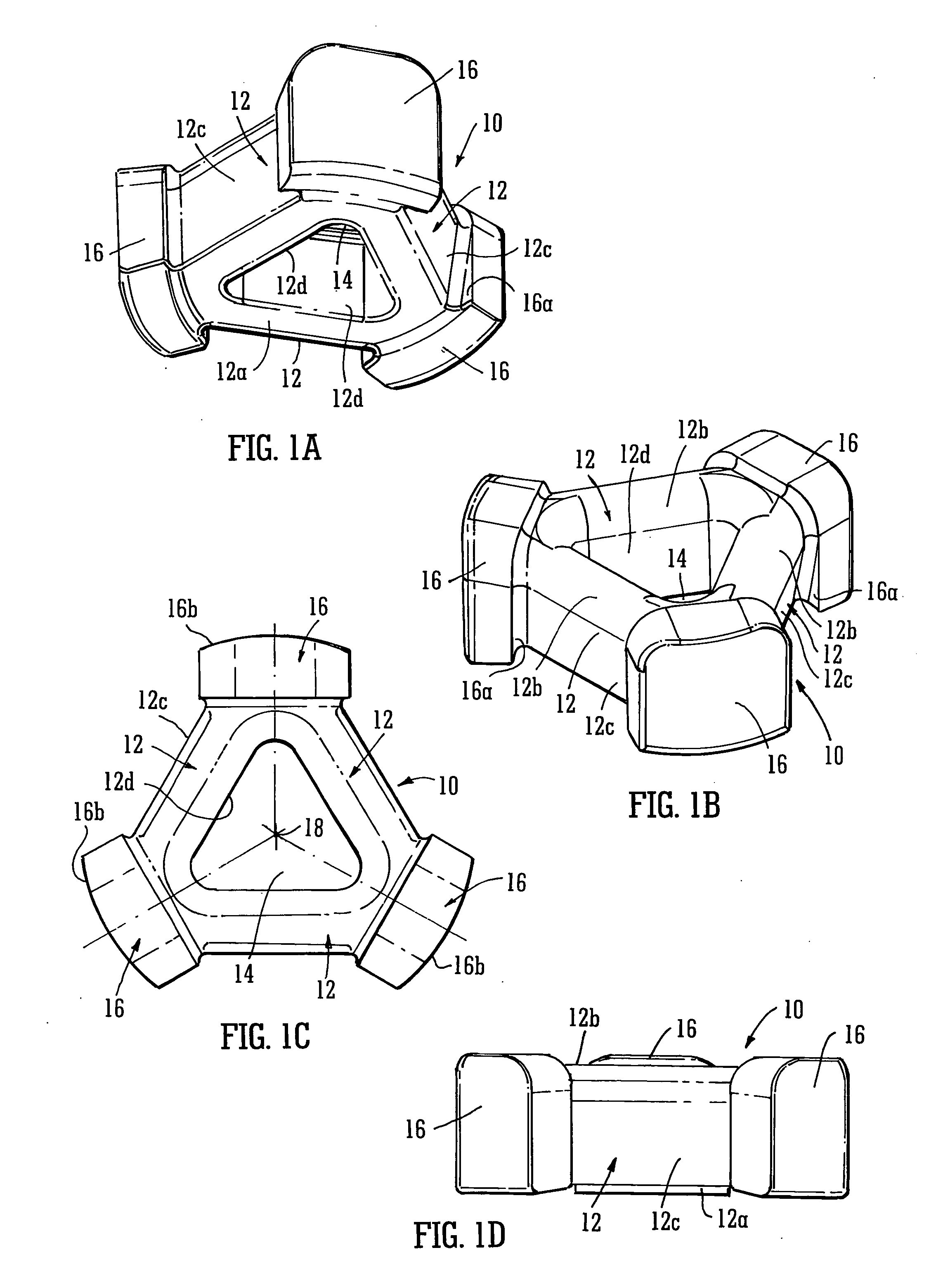
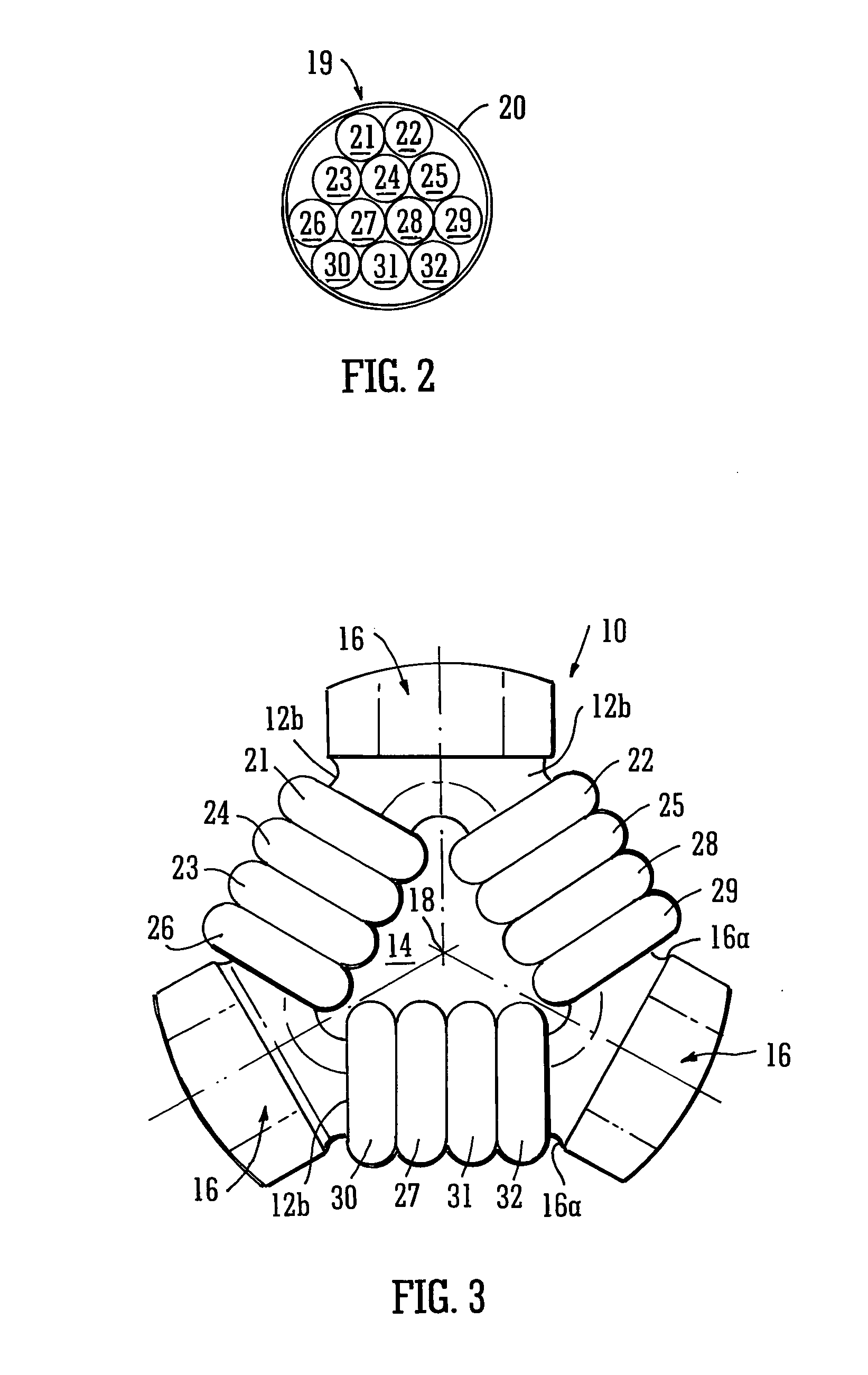
[0051]FIGS. 1A to 1D show an exemplary embodiment of a rope termination 10 according to the present invention. The rope termination 10 is for attachment to the end of a multi-core rope so that the rope may be anchored or connected to further similar multi-core ropes via a suitable rope connection assembly. As shown in the figures, the rope termination 10 comprises several load pins 12 arranged to form a closed shape around a central opening 14. In the particular embodiment shown in the figures, three identical load pins 12 are arranged in a triangular formation, however in alternative embodiments, any number of load pins 12 may be arranged into a closed shape. In particular, the closed shape may be a circle or any polygon. Since the load pins 12 of the rope termination 10 form a closed shape with a central opening 14, the rope termination 10 may be referred to as a “donut”.

[0052]Returning to the particular embodiment shown in the figures, each apex of the triangular shape has a radi...


PUM


Abstract

A rope termination (10) for a rope (19) having a plurality of sub-ropes (21-32), said rope termination comprising a connection device having a load pin (12) wherein each of said plurality of sub-ropes (21-32) is spliced into itself to form a looped end, wherein said looped ends are arranged on said load pin and each of said plurality of sub-ropes (21-32) is of equal length. The connection device further comprises a connector (34) for a rope connection assembly whereby tension is equally transferred between said load pin and each of said plurality of sub-ropes.

Description

[0001]This invention relates to rope terminations, and more particularly to rope terminations for ropes having a plurality of sub-ropes.BACKGROUND[0002]Synthetic multi-core ropes are used in a wide variety of fields, but are being increasingly used in the oil and gas industries, due to their strength and versatility. Amongst other tethering applications, multi-core ropes are used in the oil and gas industries to moor offshore facilities and anchor lines to the sea bed.[0003]Multi-core ropes can be made to withstand very heavy loads before breaking, in some cases supporting many thousands of tonnes. The strength of a multi-core rope is derived from its composition, typically being made up of many smaller fibre ropes, known as sub-ropes, that are bundled together so as to run parallel to one another along the length of the rope. Although multi-core ropes are capable of withstanding high loads, their maximum load strength is determined by their weakest point, which is often a terminati...

Claims


Application Information

Patent Timeline
IPC IPC(8): F16G11/00
CPCF16G11/00F16G15/08Y10T403/4908Y10T24/3907Y10T24/3909F16G11/046F16G11/08
Inventor THOI, HONG TRIROWLEY, DAVID STUART
Owner OFFSPRING INT
Why Eureka
Try Eureka