Knotless orthopedic stabilization system

a technology of orthopedic stabilization and knot, which is applied in the direction of internal osteosynthesis, suture equipment, osteosynthesis devices, etc., can solve the problems of inefficient placement of the assembly during surgical procedures, and achieve the effects of increasing the surface area of contact, reducing stress, and maximizing the tensile strength of the constru

Inactive Publication Date: 2020-09-17
DUNAMIS MEDICAL TECH LLC
View PDF1 Cites 3 Cited by
  • Summary
  • Abstract
  • Description
  • Claims
  • Application Information

AI Technical Summary

Benefits of technology

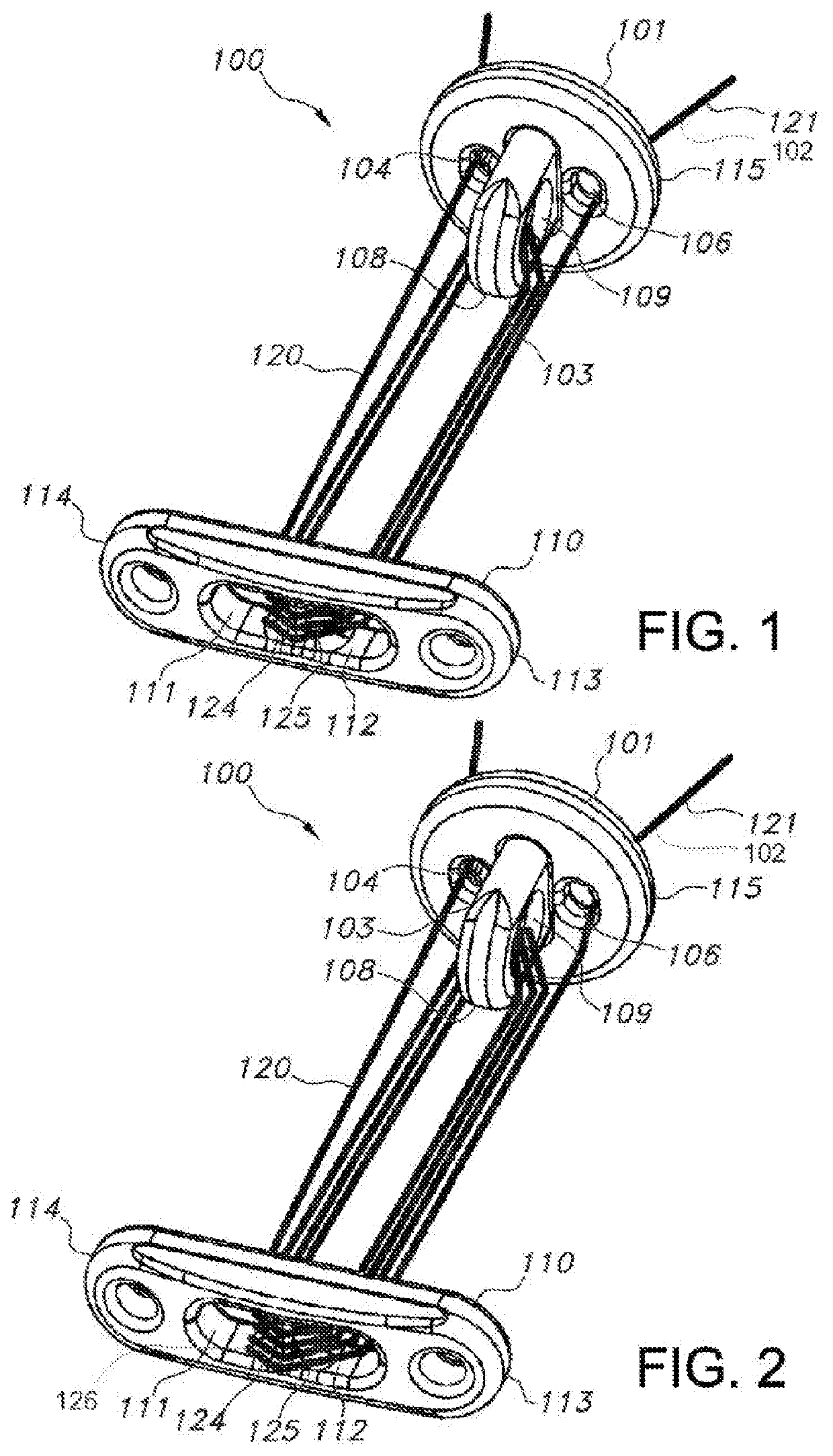
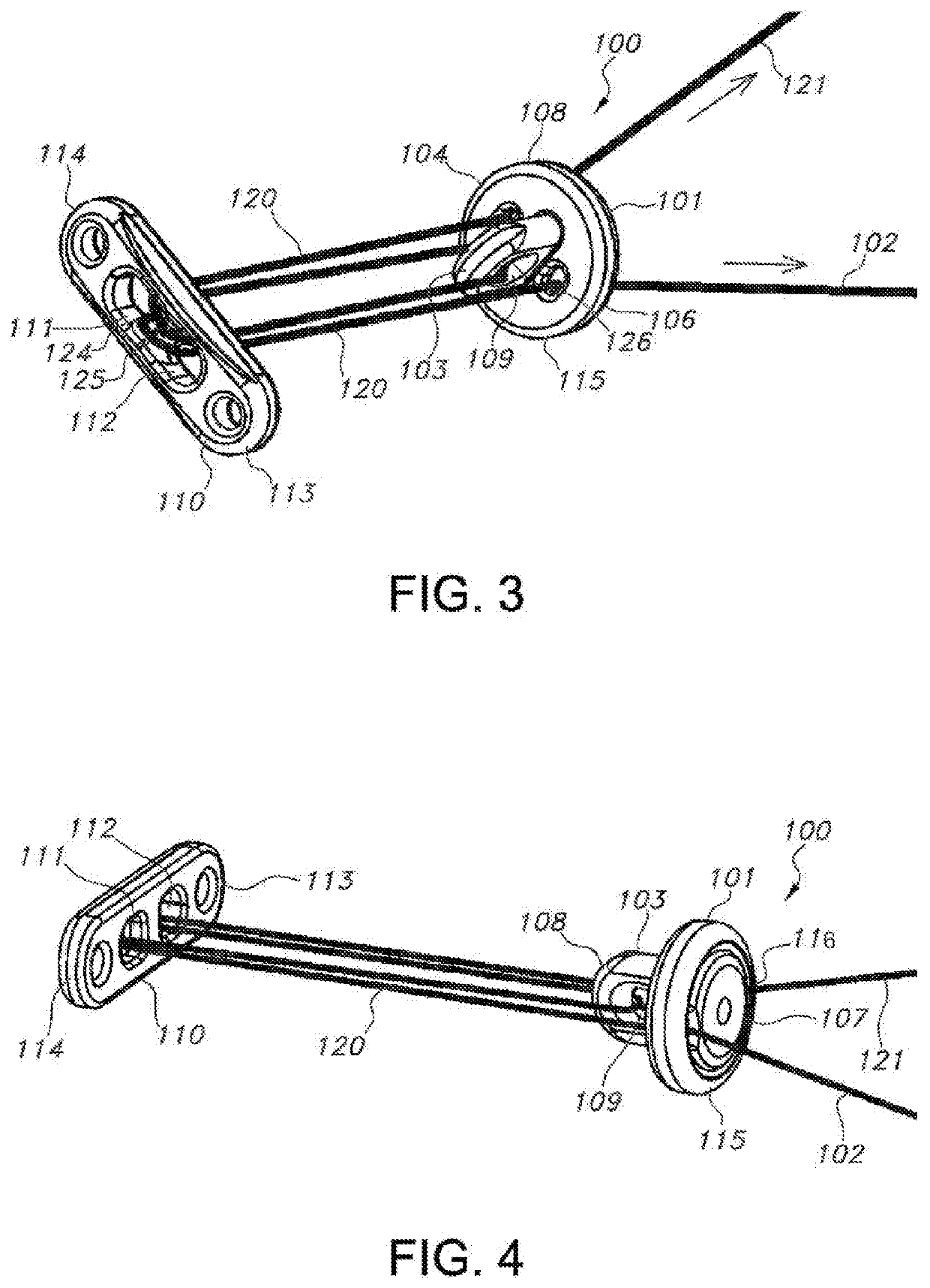
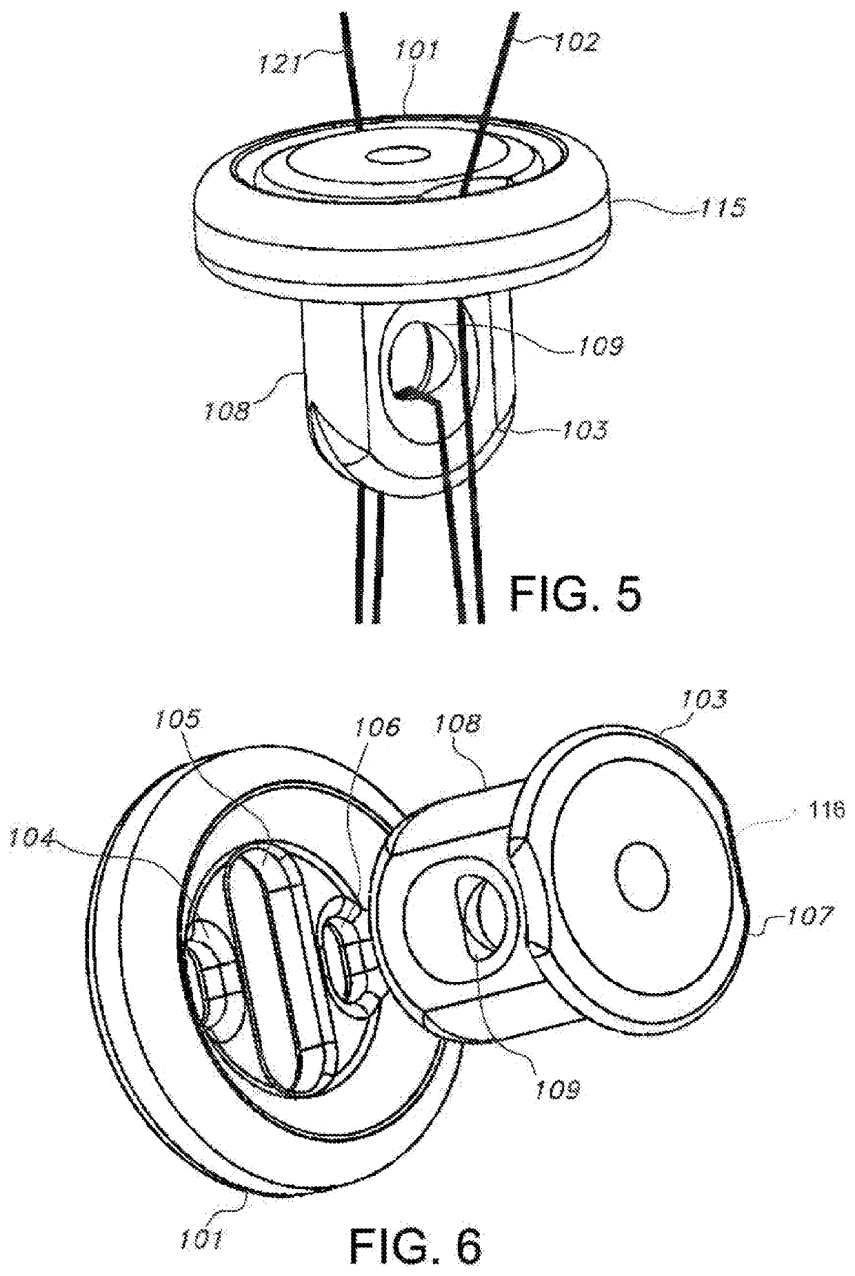
[0005]Assemblies that secure bone and tissue fragments lose tension before the assemblies can lock resulting in inefficient placement of the assembly during surgical procedures. The presently disclosed invention provides for an orthopedic stabilization device and button-suture assembly that includes suture or tensioning members on one end and a locking pin mated with a button on the other to allow tensioning and to cause an automatic locking when the applied tension is released or ceases to exist. The disclosed invention provides a mechanism that utilizes the (construct) tension generated during the tensioning step to securely lock the construct during the locking step. The locking is achieved by means of one or more pinch points designed to maximize the tensile strength of the construct by increasing the surface area of contact between the tensioning member and the locking elements (e.g. locking pin) and decreasing the stress that the tensioning member is exposed to in a locked state.

Problems solved by technology

Assemblies that secure bone and tissue fragments lose tension before the assemblies can lock resulting in inefficient placement of the assembly during surgical procedures.

Method used


Image

  • Knotless orthopedic stabilization system
  • Knotless orthopedic stabilization system
  • Knotless orthopedic stabilization system

Examples


Embodiment Construction

[0038]The following detailed description is presented to enable any person skilled in the art to make and use the invention. For purposes of explanation, specific details are set forth to provide a thorough understanding of the present invention. However, it will be apparent to one skilled in the art that these specific details are not required to practice the invention. Descriptions of specific applications are provided only as representative examples. Various modifications to the preferred embodiments will be readily apparent to one skilled in the art, and the general principles defined herein may be applied to other embodiments and applications without departing from the scope of the invention. The present invention is not intended to be limited to the embodiments shown, but is to be accorded the widest possible scope consistent with the principles and features disclosed herein.

[0039]Conventional knotted button-suture assemblies lose tension after the knot is tied on the proximal...


PUM


Abstract

Embodiments of knotless button-suture assemblies for orthopedic stabilization are disclosed. The button-suture assembly includes a button having a first opening, a second opening and a center opening. The assembly further includes a tensioning member having two tensioning member ends exiting from the first opening and the second opening of the button and disposed in the proximal direction. The assembly further includes a locking pin mated with the button through the center opening of the button in such a manner that allows a proximal movement of the tensioning member when a pulling force is applied to the tensioning member ends towards a proximal direction and prevents a distal movement of the tensioning member when the pulling force applied to the loose ends of the tensioning member ceases to exist.

Description

CROSS-REFERENCE TO RELATED APPLICATION[0001]This application claims the benefit of U.S. Provisional Application Ser. No. 62 / 817,313, filed on Mar. 12, 2019, which is incorporated herein by reference in its entirety.FIELD OF THE INVENTION[0002]The present invention is generally directed toward a device and a method for use in a surgical repair of bone or tissue. More particularly, the present invention relates to the stabilization or repair of two or more bones or tissue fragments in orthopedic procedures.BACKGROUND OF THE INVENTION[0003]Bone suspension devices, such as button-suture assemblies, that stabilize bone and tissue are known in the art. The current devices secure the bone by locking the suture or other tensioning member in place via a knot. In these procedures, after a hole is drilled through the bone, tensioning members are passed through it and fixated on the distal side of the hole. The bones are then pulled closer together and a knot is tied on the proximal side of the...

Claims


Application Information

Patent Timeline
Patent Type & Authority Applications(United States)
IPC IPC(8): A61B17/04A61B17/82A61B17/68A61B17/06
CPCA61B17/82A61B2017/0404A61B2017/0496A61B17/683A61B17/06166A61B17/0487A61B2017/0453A61B2017/0414A61B17/0401A61B2017/0403A61B2017/0458A61B2017/044A61B2017/0412A61B2017/0448
Inventor CHAVAN, M.D., PRITHVIRAJ
Owner DUNAMIS MEDICAL TECH LLC
Why Eureka
Try Eureka