Cryostat Arrangement System

A cryostat and cryocontainer technology, which is applied to instruments, measuring devices, household refrigeration devices, etc., can solve the problem that the cryostat cannot be used

Active Publication Date: 2020-12-04
BRUKER SWITZERLAND AG
View PDF14 Cites 0 Cited by
  • Summary
  • Abstract
  • Description
  • Claims
  • Application Information

AI Technical Summary

Problems solved by technology

The walls of the neck tube should be airtight so that the vacuum isolation of the cryostat does not become contaminated and cause it to become unusable

Method used


Image

  • Cryostat Arrangement System
  • Cryostat Arrangement System
  • Cryostat Arrangement System

Examples


Embodiment Construction

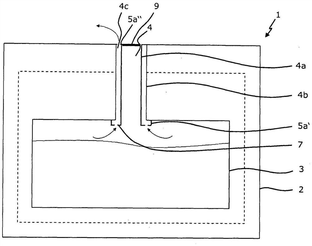
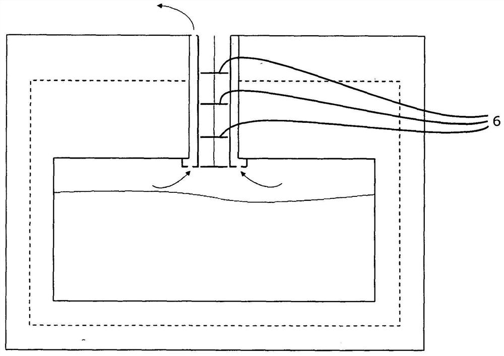
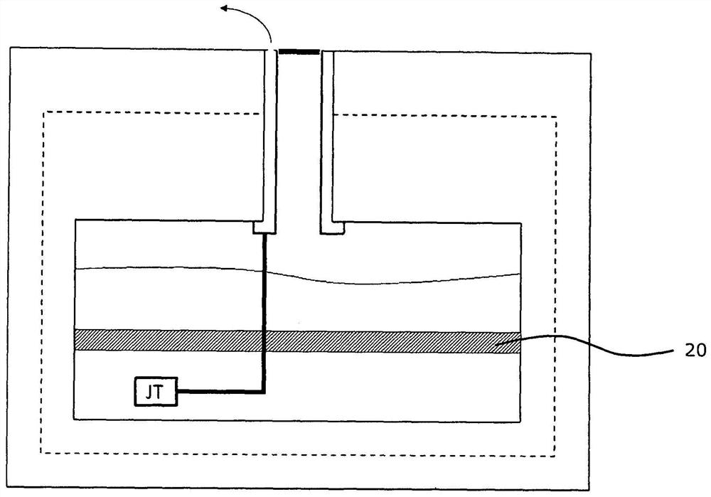
[0045] in the attached Figures 1 to 4 shows a schematic view of a preferred embodiment of a cryostat arrangement according to the invention for storing fluid cryogenics, in particular a magnet arrangement for cooling superconductors.

[0046] Such a cryostat arrangement 1 has a vacuum vessel 2 and a cryocontainer 3 arranged inside the vacuum vessel 2, wherein the vacuum vessel 2 has at least one neck 4 which has a support structure 4a and surrounds the support structure 4a. The outer tube 4b of the outer tube 4b, wherein the neck tube 4 leads to the cryogenic container 3 and the space connection between the inner volume of the cryogenic container 3 and the area outside the vacuum container 2 can be established through the neck tube 4, so that the cryogenic fluid can flow from the cryogenic container 3 to the vacuum container 2 flows in the outer region or vice versa.

[0047] The cryostat arrangement 1 according to the invention is characterized in relation to the known devi...


PUM


Abstract

The invention relates to a cryostat arrangement (1) comprising a vacuum vessel (2) and a cryogenic vessel (3) arranged therein, the vacuum vessel having a neck (4) leading to the cryogenic vessel, the neck comprising a support structure (4a) and an outer tube (4b) surrounding the support structure, the connection of the cryogenic vessel to the area outside the vacuum vessel is established via a neck tube so that the cryogenic fluid flows from the cryogenic vessel into the area outside the vacuum vessel or vice versa, wherein, The part of the neck tube for mechanically suspending the cryogenic vessel on the vacuum vessel and the part of the neck tube for creating a diffusion barrier between the interior of the cryogenic vessel and the interior of the vacuum vessel are arranged spatially apart from each other And are each made of differently optimized materials.

Description

technical field [0001] The invention relates to a cryostat arrangement with a vacuum vessel and a cryocontainer arranged inside the vacuum vessel, wherein the vacuum vessel has at least one neck tube with a support structure and an outer tube surrounding the support structure, wherein the neck leads to the cryocontainer and a spatial connection of the inner volume of the cryocontainer to the region outside the vacuum vessel can be established via the neck tube, whereby The cryogenic fluid may flow from the cryogenic container into an area outside the vacuum container or vice versa. Background technique [0002] Such a cryostat arrangement is known, for example, from US-A 5,220,800. [0003] The present invention generally relates to the field of cooling technical systems which should / must be kept at very low (=low temperature) temperatures during operation. Such systems may include, for example, superconducting magnet arrangements, such as are used, for example, in the fie...

Claims


Application Information

Patent Timeline
Patent Type & Authority Patents(China)
IPC IPC(8): F17C13/00
CPCF17C13/002G01R33/3804G01R33/3815F25B19/005F25B2309/02F25D19/00F25D23/06F25D2201/14
Inventor P·维库斯S·博恩
Owner BRUKER SWITZERLAND AG
Why Eureka
Try Eureka