Turbine blade with tip section cooling

a turbine blade and tip section technology, applied in the direction of liquid fuel engines, vessel construction, marine propulsion, etc., can solve the problems of limited cooling capability of the first-stage blade, air foils, and the cooling capacity of the suction side squealer tip rail, so as to reduce section heat load, improve cooling, and improve efficiency

Inactive Publication Date: 2011-11-29
FLORIDA TURBINE TECH
View PDF21 Cites 54 Cited by
  • Summary
  • Abstract
  • Description
  • Claims
  • Application Information

AI Technical Summary

Benefits of technology

[0013]It is another object of the present invention to provide for a turbine rotor blade with a tip rail on the suction side that creates a cooling air flow vortex to trap the cooling flow longer than in the prior art in order to provide better cooling for the tip rail.
[0014]It is another object of the present invention to provide for a turbine rotor blade with a tip rail in which the blade tip section cooling air flow and bla

Problems solved by technology

However, the highest turbine inlet temperature is limited to the airfoil materials and the cooling capability of the first stage blades and vanes.
Another problem with high temperature exposure to the turbine air foils is from erosion due to the hot gas flow acting on a section of the blade tip that is not adequately cooled.
Since the blade tip region is subject to severe secondary flow, a large number of film cooling holes and cooling flow is required for the cooling of the blade tip periphery.
Cooling of the suction side squealer tip rail by means off a row of discharge film cooling holes located along the blade suction side peripheral and at the bottom of the squealer floor becomes

Method used


Image

  • Turbine blade with tip section cooling
  • Turbine blade with tip section cooling
  • Turbine blade with tip section cooling

Examples


Embodiment Construction

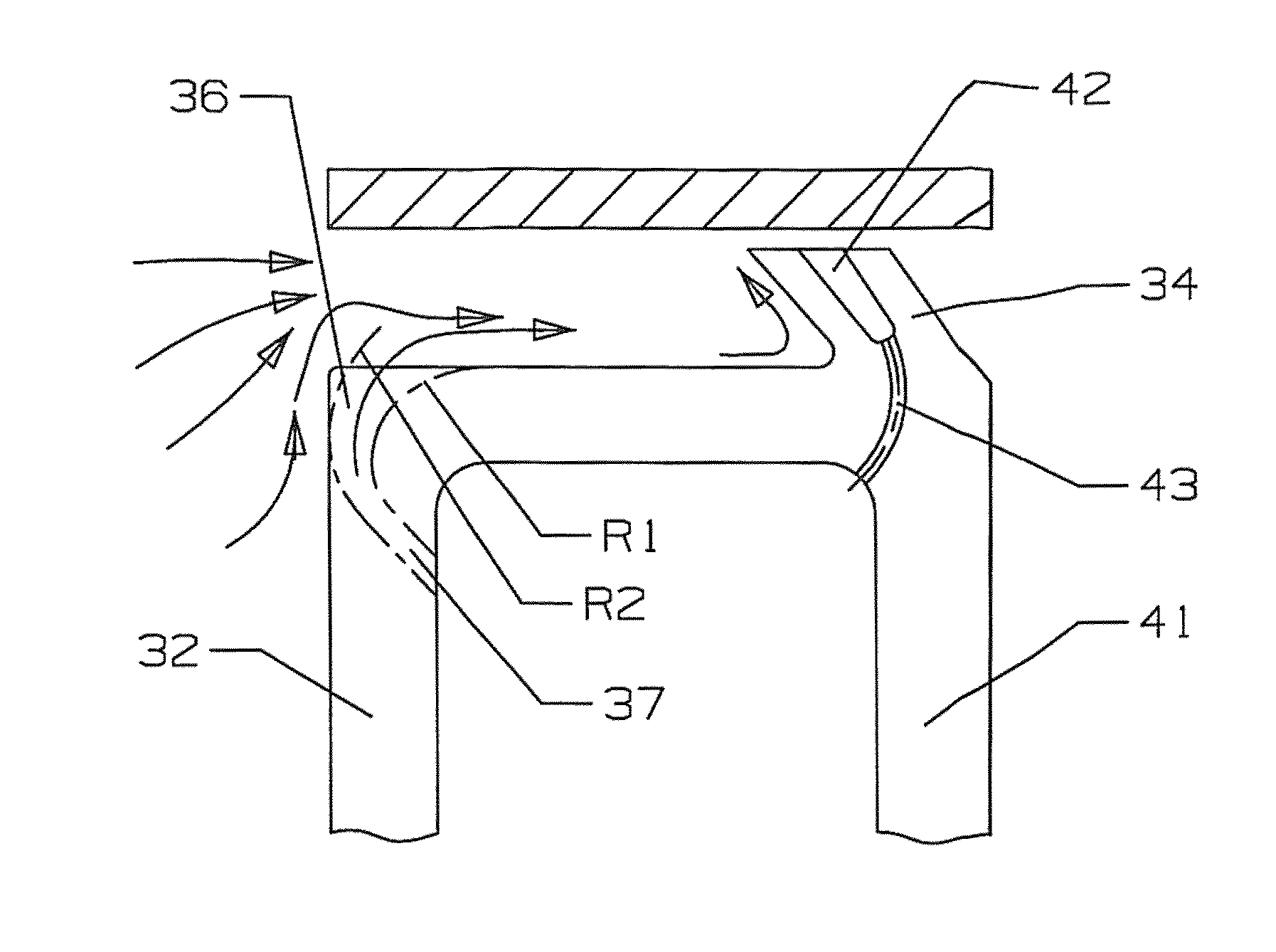
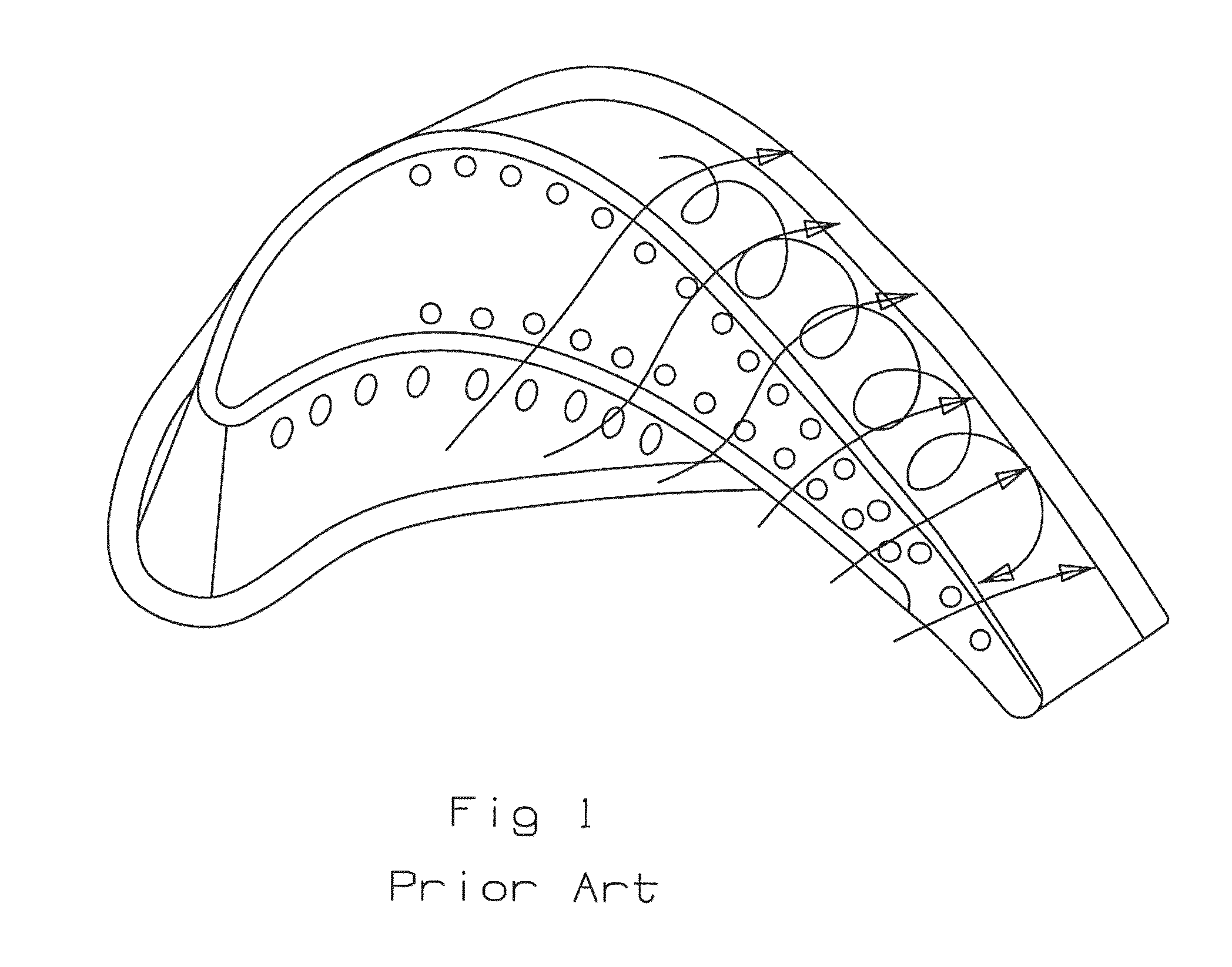
[0030]The turbine rotor blade with the tip cooling circuit of the present invention is shown in FIGS. 6-13 where FIG. 6 shows the blade tip from a top view on the pressure wall side and includes a leading edge 31, a pressure side wall 32, a trailing edge 33a suction side tip rail 34 that extends from the trailing edge and around the leading edge 31 and ends just down from the leading edge region on the pressure side wall 32 as seen in FIG. 6. A tip floor 35 closes off the blade tip and forms a squealer pocket with the tip rail 34. A row of pressure side trenches 36 extends along the pressure side wall and the tip between the ending of the tip rail 34 and the trailing edge 33. Each trench 36 is connected to a cooling air supply channel formed within the body of the airfoil by a metering hole 37. Each of the trenches 36 each are formed by an upstream side wall with a radius of curvature of R3 and a downstream side wall with a radius of curvature of R4 as seen in FIG. 7.

[0031]FIG. 8 sh...


PUM


Abstract

A turbine rotor blade with a single tip rail on the suction side of the blade tip, and in which the pressure side tip edge includes a row of trench film slots that each having side walls that are open on the pressure side wall and extend onto the tip floor and have side walls with a curvature toward the trailing edge of the blade tip. The trench film slots also have a curved inboard surface and a curved outboard surface in which the inboard surface curvature is less than the outboard surface curvature. The tip rail includes a slot opening onto the top surface and extending the length of the tip rail with a row of metering and cooling holes opening into the slot. The metering and cooling holes have a curvature toward the pressure side edge of the tip floor to increase a heat transfer rate form the metal.

Description

FEDERAL RESEARCH STATEMENT[0001]None.CROSS-REFERENCE TO RELATED APPLICATIONS[0002]None.BACKGROUND OF THE INVENTION[0003]1. Field of the Invention[0004]The present invention relates generally to a gas turbine engine, and more specifically to a turbine rotor blade tip section with cooling and sealing.[0005]2. Description of the Related Art including information disclosed under 37 CFR 1.97 and 1.98[0006]A gas turbine engine, especially an industrial gas turbine (IGT) engine, includes a turbine section with a number of rows or stages or rotor blades and stator vanes to react with a hot gas flow to power the engine. The efficiency of the engine can be increased by passing a higher temperature gas flow into the turbine. However, the highest turbine inlet temperature is limited to the airfoil materials and the cooling capability of the first stage blades and vanes. An improvement in the material properties or to provide better cooling to allow for higher temperatures will allow for higher ...

Claims


Application Information

Patent Timeline
IPC IPC(8): F01D5/18
CPCF01D5/186F01D5/187F01D5/20F05D2260/202
Inventor LIANG, GEORGE
Owner FLORIDA TURBINE TECH
Why Eureka
Try Eureka