Cooling structure an electric vehicle

a technology for electric vehicles and cooling structures, applied in domestic cooling apparatuses, cell components, secondary cells servicing/maintenance, etc., can solve problems such as cost increase and adverse effect on the reliability and durability of electric parts

Inactive Publication Date: 2000-08-01
HONDA MOTOR CO LTD
View PDF8 Cites 243 Cited by
  • Summary
  • Abstract
  • Description
  • Claims
  • Application Information

AI Technical Summary

Problems solved by technology

If the cooling air obtained utilizing the outside air as it is, is applied directly to a delicate electric part, there is a possibility that an adverse effect may be exerted to the reliability

Method used


Image

  • Cooling structure an electric vehicle
  • Cooling structure an electric vehicle
  • Cooling structure an electric vehicle

Examples


second embodiment

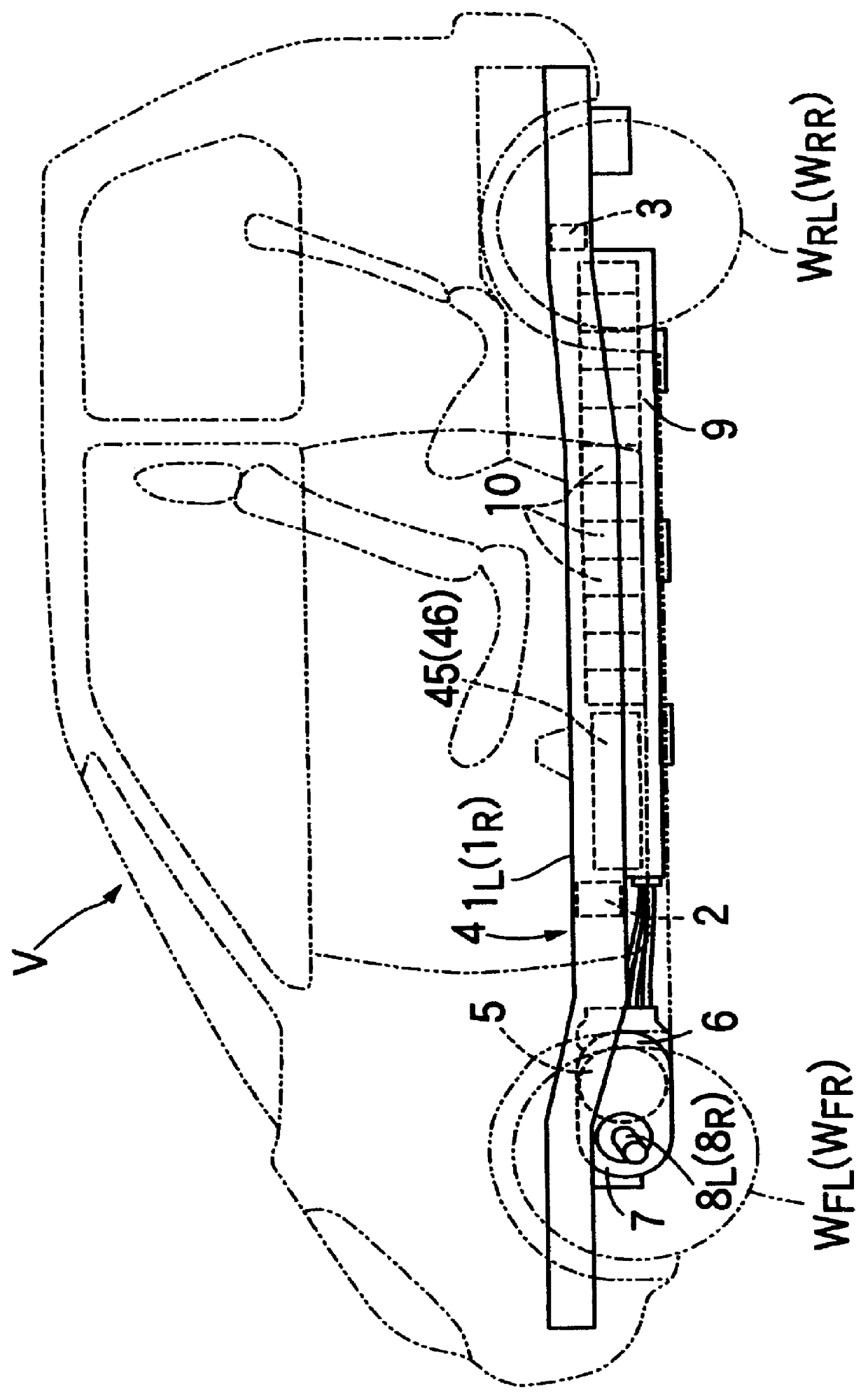
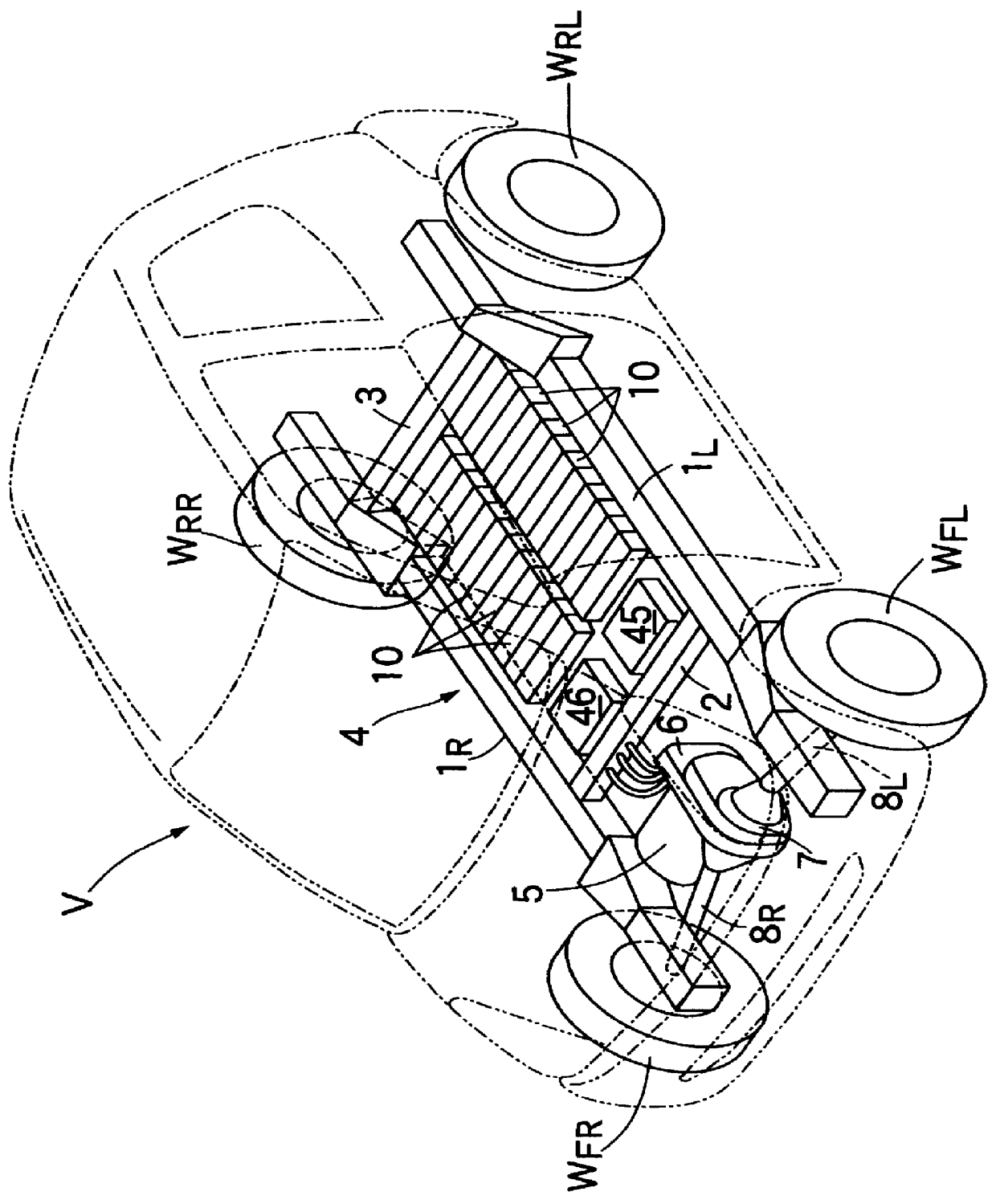
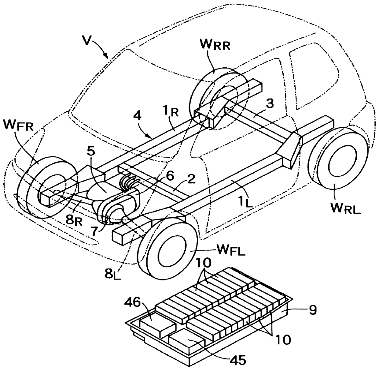
The second embodiment includes an auxiliary cooling chamber 51 on a portion of an upper surface of the floor panel 36, above a rear portion of a battery box 9. The auxiliary cooling chamber 51 is divided into an upper electric part accommodating chamber 53 and a lower,third cooling air passage 54. Electric parts 46 and 55 and a cooling fan 40' are accommodated in the electric part accommodating chamber 53. The electric part 46 is an on-board charger 25, and the electric part 55 is a downverter 26.

The third cooling air passage 54 is curved into a substantially C-shape as viewed in a plane (FIG. 9). The cooling fan 40' is connected to an upstream end of the third cooling air passage 54, and a downstream end of the third cooling air passage 54 communicates with an upstream end of the first cooling air passage 39' within the battery box 9' through three openings 56. Cooling fins 46.sub.1 and 55.sub.1 extending downwards from the electric parts 46 and 55 accommodated in the electric part...


PUM


Abstract

An electric vehicle includes plurality of batteries accommodated in a rear portion of a battery box, and an electric part is accommodated in an electric part accommodating chamber provided in a front portion of the battery box. Cooling air supplied from a cooling fan to the rear portion of the battery box cools the batteries having a large thermal resistance, while being passed through a first cooling air passage around outer peripheries of the batteries at a low flow rate. A second cooling air passage having a smaller sectional area than that of the first cooling air passage is provided below the electric part accommodating chamber, and cooling fins protruding downwards from the electric part are exposed within the second cooling air passage. The second cooling air passage extends continuously the first cooling air passage in a downstream direction of airflow, so that cooling air which has first cooled the batteries then cools the electric part having a smaller thermal resistance, while being passed through the second cooling air passage at a higher flow rate than that in the first cooling air passage.

Description

1. Field of the InventionThe present invention relates to a cooling structure in an electric vehicle for cooling batteries and / or an electric part cooling air from a cooling fan.2. Description of the Related ArtIn a conventional electric vehicle including batteries disposed below a floor panel, electric parts such as a motor controller, a PDU and the like are disposed in an engine compartment or other vehicle compartment, and correspondingly a cooling fan for cooling the batteries and a cooling fan for cooling the electric parts are provided separately.If the batteries and the electric parts are disposed in different places as described above, a plurality of cooling fans are required. Therefore, if the batteries and the electric part were mounted within a battery box and they are cooled collectively by a common cooling fan, the number of cooling fans can be reduced.In this regard the effect of cooling air on the batteries each having a battery case made of a synthetic resin with a l...

Claims


Application Information

Patent Timeline
IPC IPC(8): B60H1/00B60L11/18H01M10/42H01M10/50H01M2/10B60K11/06B60L50/64H01M10/60H01M10/613H01M10/625H01M10/652H01M10/6556H01M10/6557H01M10/6563
CPCB60H1/00278B60K1/04B60L3/0046B60L11/1874B60L11/1877H01M2/1077H01M2/1083H01M10/5004H01M10/5016H01M10/5032H01M10/5067H01M10/5097Y02T10/7005B60L2250/10B60L2250/16H01M2/1016B60H2001/003H01M10/625H01M10/6563H01M10/647H01M10/667H01M10/613B60L58/26B60L50/66Y02T10/70Y02E60/10H01M50/249B60L50/64H01M50/209
Inventor ANAZAWA, MAKOTOAITAKA, KAZUHIKOWATANABE, KAZUNORI
Owner HONDA MOTOR CO LTD
Why Eureka
Try Eureka