Lighting device for a medical or dental instrument

a technology for lighting devices and applied in the field of medical or dental instruments, can solve the problems of increasing the space required for lighting devices in or on instruments, creating lighting devices with reduced external dimensions, etc., and achieves the reduction and the addition of the outside diameter or outside cross section of the lighting device.

Active Publication Date: 2014-05-15
W&H DENTALWERK
View PDF6 Cites 15 Cited by
  • Summary
  • Abstract
  • Description
  • Claims
  • Application Information

AI Technical Summary

Benefits of technology

[0012]Using a socket made of a ceramic material or a glass ceramic material or glass, a hollow metallic sleeve and in particular using a material comprising metal and glass and/or a casting material or adhesive material for attaching the socket and the sleeve eliminates the need to provide the socket and the sleeve with a flange and a mating flange so that the outside diameter or outside cross-section of the lighting device are reduced. According to the embodiment the wall thickness of the sleeve wall of the hollow metallic sleeve is sufficient to connect the socket and the sleeve to one another, in particular to connect them together tightly to be able to form a sealed chamber for the at least one optical semiconductor element. The socket may have a round or angular external shape, for example, a rectangular, hexagonal or octagonal shape.
[0013]A further reduction in the outside diameter or outside cross section of the li

Problems solved by technology

However, the encapsulation causes the lighting device to be larger and thus also increases the space required for the lighting device in or on the instrument.
There is thus the problem of creating a lighting device having reduced external dimensions while retaining the well-proven design encompassing the socket, the cap, the light-dispensing window and the encapsulated interior in order to enable or facilitate the arrangement of one or more such lighting devices in or on the medical or dental, instrument

Method used


Image

  • Lighting device for a medical or dental instrument
  • Lighting device for a medical or dental instrument
  • Lighting device for a medical or dental instrument

Examples


Embodiment Construction

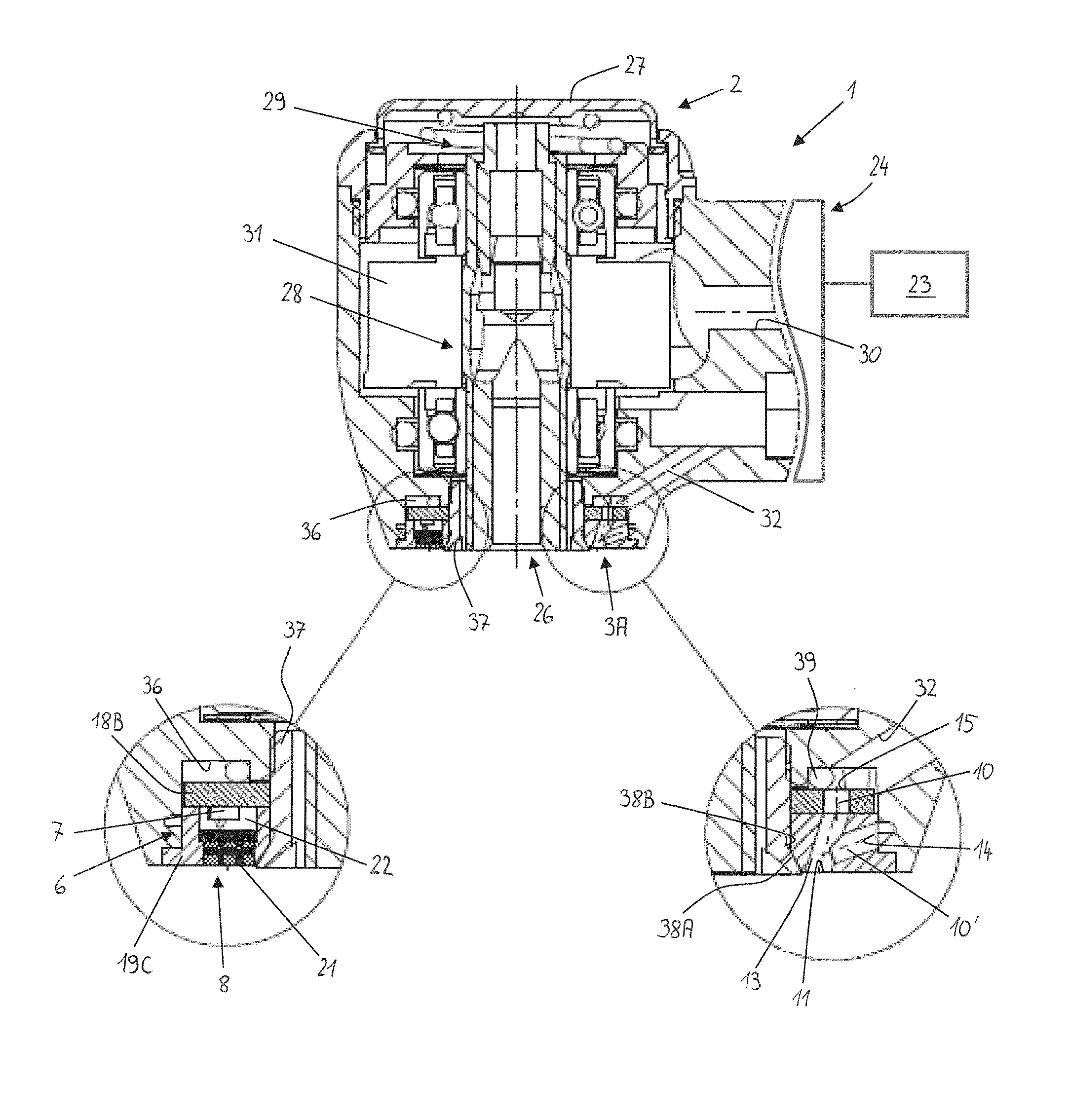
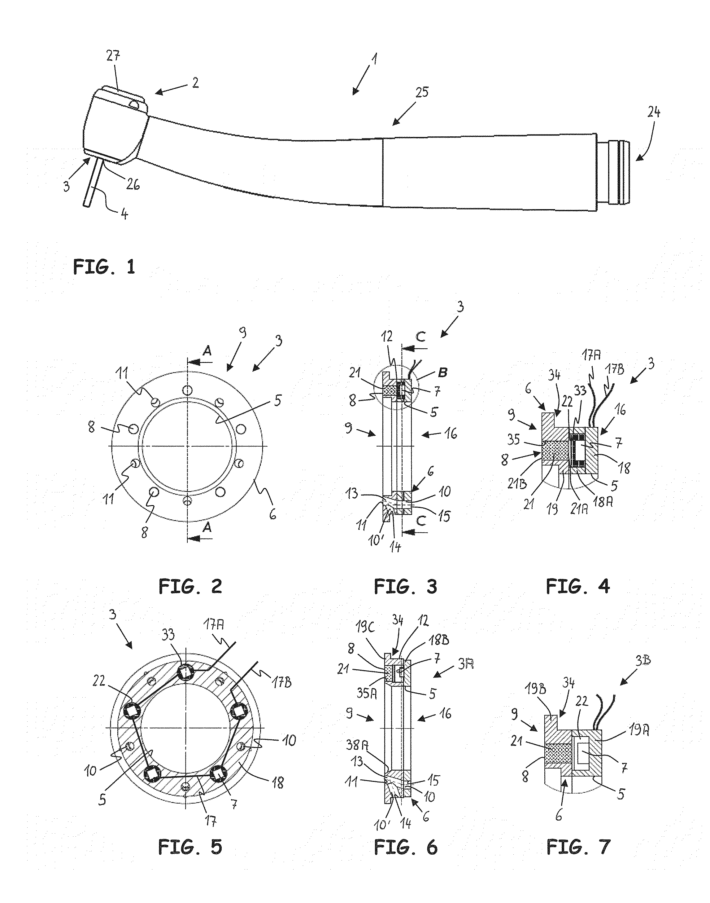
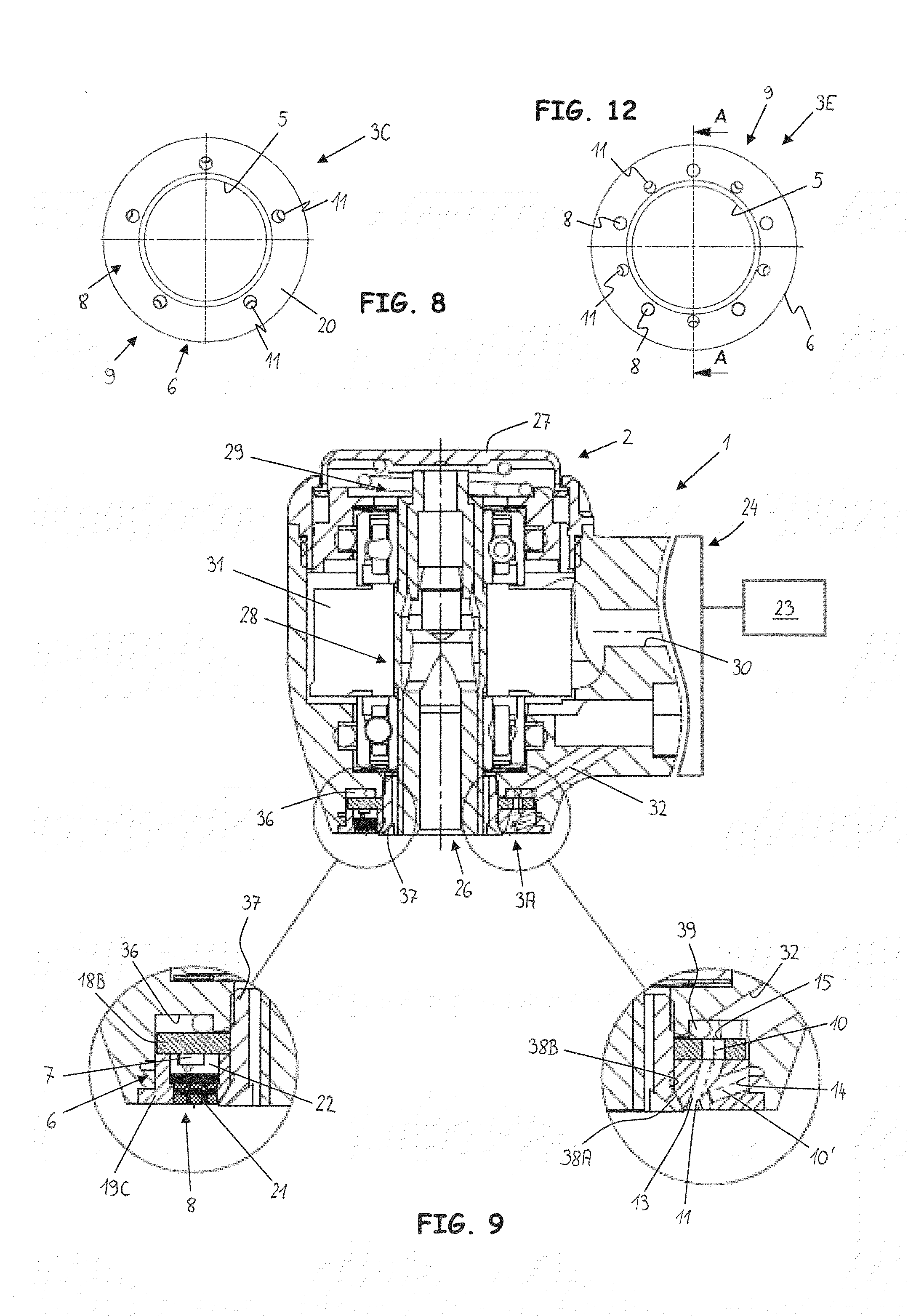
[0098]The medical or dental, instrument 1 shown in FIGS. 1 and 9 is designed as an elongated tubular instrument 1 or handpiece which has at one end a connection 24 for detachable connection, for example, to a control device, a drive unit, a power source and / or a fluid source, in particular a water and / or compressed air source. The instrument 1 comprises a handle part 25, which is bent or has two sections arranged at an angle to one another and also has an instrument head 2 connected to the former. A tool opening 26 is provided on the instrument head 2, wherein a tool 4 for acting on a treatment site can be introduced detachably into the instrument head 2 through this tool opening 26. A detachable tool-mounting device 28, for example, a chuck, is arranged in the instrument head 2, securing the tool 4 detachably on the instrument head 2. The tool opening 26 is arranged on the side of the instrument head 2 so that the tool 4 protrudes out of the instrument head 2 at an angle to the han...


PUM


Abstract

Medical or dental instruments having a lighting device, manufacturing methods for such instruments and various lighting devices having an optical semiconductor element are described. The lighting devices have, for example, a body, at least one radiation-emitting surface on a radiation-emitting end of the body and at least one fluid channel which is provided in the body and connects at least one opening which is provided on the radiation-emitting end to one or more fluid sources for dispensing fluid. The lighting devices have, for example, a hollow metallic sleeve, a transparent window for emission of electromagnetic radiation and a socket on which at least one optical semiconductor element is arranged. The socket is made of a ceramic, glass ceramic or glass material, and is connected to the hollow metallic sleeve by a material comprising metal and glass.

Description

CROSS REFERENCE TO RELATED APPLICATION[0001]The present application is a continuation of copending International Patent Application No. PCT / EP2012 / 064127, filed Jul. 19, 2013, and claims priority from pending European Patent Application No. 11174505.5, filed Jul. 19, 2011, which are incorporated herein by reference.BACKGROUND[0002]1. Field[0003]The present application relates to a lighting device for a medical or dental instrument, in particular for an instrument head of such an instrument, having at least one semiconductor element which is designed for emission of electromagnetic radiation, in particular radiation in the visible wavelength range.[0004]2. Description of Prior Art[0005]A lighting device for a medical or dental instrument is known from German Utility Model DE 20 202 020 763 U1, for example. This lighting device comprises a metallic cap with a light-dispensing window and a metallic socket welded to the metallic cap so that an encapsulated interior is formed by the cap ...

Claims


Application Information

Patent Timeline
IPC IPC(8): A61B19/00A61C17/02A61M3/02A61C1/08
CPCA61B19/5202A61C1/088A61M3/02A61C17/0217A61C17/0202A61C17/02A61B90/30F04C2270/0421A61B90/35F21V33/0068
Inventor HEINRICH, CHRISTOPHJINDRA, THOMAS
Owner W&H DENTALWERK
Why Eureka
Try Eureka