Rotation angle detector

a detector and rotation angle technology, applied in the direction of instruments, mechanical measuring arrangements, using mechanical means, etc., can solve the problems of power consumption increase, absolute steer angle calculated up to then is lost, and the installation space of the detector is reduced, so as to achieve high accuracy and reduce the effect of installation spa

Inactive Publication Date: 2005-02-01
KK TOKAI RIKA DENKI SEISAKUSHO
View PDF10 Cites 43 Cited by
  • Summary
  • Abstract
  • Description
  • Claims
  • Application Information

AI Technical Summary

Benefits of technology

The objectives of the present invention are to provide a rotation angle detector that detects an absolute rotation angle of a rotating body with high accuracy and allows for reducing the installation space thereof.

Problems solved by technology

However, in the case of detecting the absolute steer angle of the steering wheel with the incremental signal encoder, when the power supply to the electronic control unit is stopped due to switching the ignition switch of the vehicle off, the absolute steer angles calculated up to then are lost.
Therefore, when the ignition switch is switched on again, the steer angle cannot immediately be detected.
In this case, the power consumption increases since the power source must be supplied to the electronic control unit while the ignition switch is switched off.
As a result, the installation of the rotation angle detector in a vehicle becomes difficult.
The difficulty of the installation becomes increasingly pronounced as the rotation range of the steering shaft ST increases.

Method used


Image

  • Rotation angle detector
  • Rotation angle detector
  • Rotation angle detector

Examples


first embodiment

(First Embodiment)

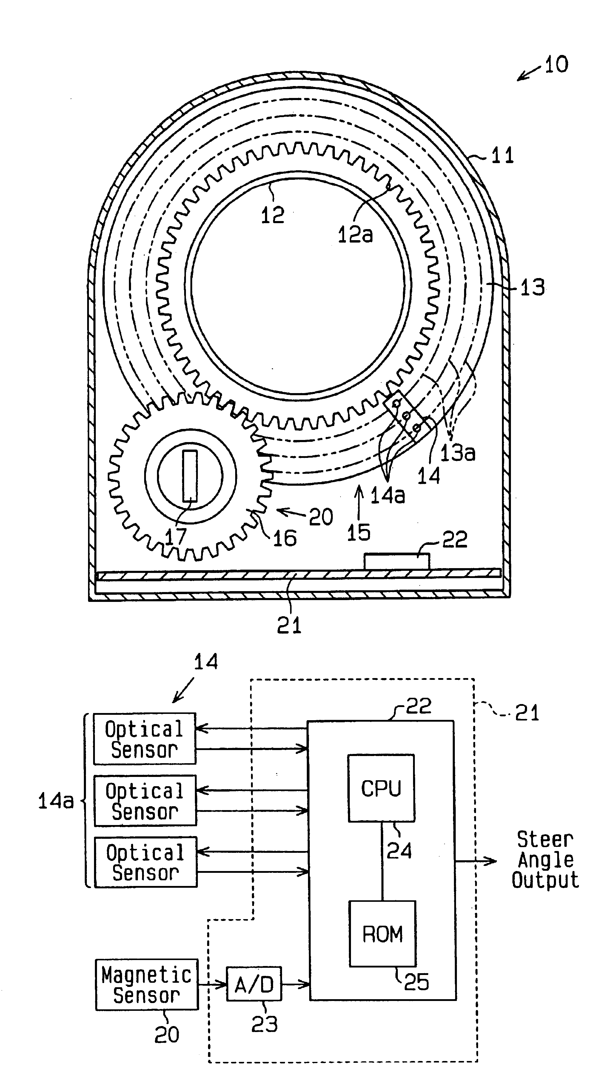
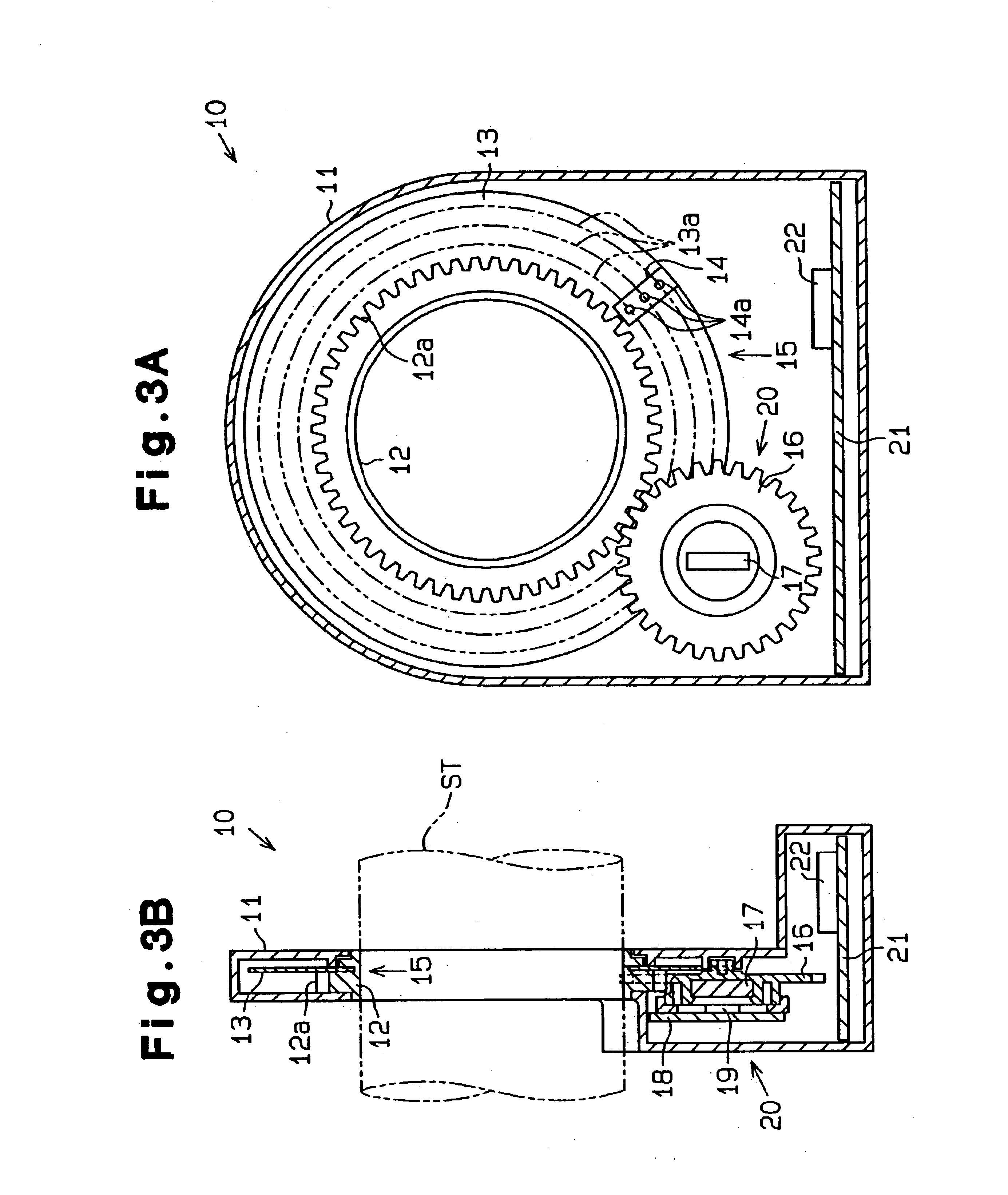
According to the first embodiment, the rotation angle detector 10 is used as a steer angle detector that detects an absolute steer angle of a steering wheel of a vehicle.

As shown in FIG. 3A and FIG. 3B, the steer angle detector 10 is fixed to a steering shaft (a detection body) ST. The steer angle detector 10 includes a housing 11, an absolute signal encoder (a first rotation angle detector) 15, a magnetic sensor 20, and a circuit board 21. The housing 11 is fixed to a structure surrounding the steering shaft ST. The absolute signal encoder 15, the magnetic sensor 20 (a second rotation angle detector), and the circuit board 21 are accommodated in the housing 11.

The absolute signal encoder (hereafter referred to as “encoder”) 15 includes a rotary shaft 12, a rotating plate (a first rotating body) 13, and an optical sensor array 14. The rotary shaft 12 is rotatably supported by the housing 11. The rotary shaft 12 is fixed to the steering shaft ST with the rotary shaf...

second embodiment

(Second Embodiment)

FIG. 9 is a schematic perspective view of a rotation angle detector 50 of the second embodiment according to the present invention. As shown in FIG. 9, the rotation angle detector 50 includes a rotating plate 51 and four optical sensors 52a, 52b, 52c, and 52d that are provided opposed to both surfaces of the rotating plate 51.

The rotating plate 51 is fixed to a rotary shaft (e.g., a steering shaft in which the absolute steer angle is detected) ST with the rotating plate 51 being fitted onto the rotary shaft ST. When the rotary shaft ST rotates, the rotating plate 51 rotates together with the rotary shaft ST about the axis X of the rotary shaft ST.

Each of optical sensors 52a-52d is fixed to a support (not shown) of the rotary shaft ST. In the second embodiment, the optical sensors 52a and 52c function as a first detection device and the optical sensors 52b and 52d function as a second detection device.

As shown in FIG. 10, the rotating plate 51 includes an annular d...

third embodiment

(Third Embodiment)

FIG. 18 is a schematic cross-sectional view of a rotation angle detector 60 of the third embodiment according to the present invention. In the third embodiment, the rotation angle detector 60 is used as a steer angle detector for detecting an absolute steer angle of a steering wheel of a vehicle.

As shown in FIG. 18, only an absolute signal encoder and a computer of the steer angle detector 60 are different from those of the steer angle detector 10 shown in FIG. 3A. An absolute signal encoder 65 (a first rotation angle detector) and a computer 62 of the steer angle detector 60 can be replaced with the absolute signal encoder 15 and a computer 22 shown in FIG. 3A, respectively.

The absolute signal encoder 65 (hereafter referred to as “encoder”) includes a rotary shaft 12, a rotating plate (a first rotating body) 51 shown in FIG. 9 and four optical sensors 52a-52d.

The rotary shaft 12 is rotatably supported by the housing 11. The rotary shaft 12 is fixed to the steerin...


PUM


Abstract

A rotation angle detector that is able to detect an absolute rotation angle of a detection body accurately and is able to reduce the installation space required. The rotation angle detector includes a first rotation angle detector connected to the detection body for generating a first detection signal having a cycle corresponding to the rotation of the detection body. The first rotation angle detector includes a first rotating body which is connected to the detection body and rotates together with the detection body. The detector includes a second rotation angle detector connected to the first rotation angle detector. The second rotation angle detector includes a second rotating body that rotates together with the first rotating body at a rate greater than that of the first rotating body, and generates a second detection signal having a cycle corresponding to the rotation of the second rotation body. The control device detects an absolute rotation angle of the detection body in accordance with the first detection signal and the second detection signal.

Description

TECHNICAL FIELDThe present invention relates to a rotation angle detector for detecting an absolute rotation angle of a rotating body. More specifically, the present invention relates to a rotation angle detector for detecting an absolute steer angle of a steering wheel, for example, in a vehicle.BACKGROUND ARTThe conventional rotation angle detector has an incremental signal encoder for detecting an absolute steer angle (e.g., 720° when steered in the right direction) of a steering wheel that makes multiple rotations. As shown in FIG. 1, an incremental signal encoder 100 includes a rotating plate 40 connected to a steering shaft ST and optical sensor arrays 41 for detecting a slit array (not shown) provided for the rotating plate 40.When the rotating plate 40 rotates due to steering of the steering wheel, the encoder 100 sequentially detects each slit of the slit array and produces an associated pulse signal that corresponds to each sensed slit. The pulse signal is supplied to an e...

Claims


Application Information

Patent Timeline
Patent Type & Authority Patents(United States)
IPC IPC(8): G01D5/36G01D5/12G01D5/249G01D5/26
CPCG01D5/2492G01D5/363G01D5/36
Inventor ITO, SHIGEJIFUTAMURA, YASUHIKONITTA, SHIGENORIARAKI, MIKIHISA
Owner KK TOKAI RIKA DENKI SEISAKUSHO
Why Eureka
Try Eureka