Drive train for a hybrid motor vehicle

a hybrid and drive train technology, applied in the direction of transmission elements, belts/chains/gearrings, toothed gearings, etc., to achieve the effect of high efficiency, avoiding drag torque, and optimizing the efficiency chain

Active Publication Date: 2016-03-24
DR ING H C F PORSCHE AG
View PDF22 Cites 33 Cited by
  • Summary
  • Abstract
  • Description
  • Claims
  • Application Information

AI Technical Summary

Benefits of technology

[0010]The electric machine can be coupled to at least one auxiliary unit via an auxiliary shaft, which is spaced apart radially from the engine shaft and can be coupled to the intermediate shaft, wherein, in particular, the auxiliary shaft is spaced apart radially from the internal combustion engine. This makes it possible to drive auxiliary units, e.g. an oil pump, water pump, air conditioning compressor of an air conditioning system or the like, mechanically, in particular via a belt drive, with the aid of the electric machine even when the internal combustion engine is switched off. In addition, the internal combustion engine can have a torque output, e.g. a belt pulley or chain wheel connected to the engine shaft, in order to drive the auxiliary units mechanically via the same mechanical link as that also used by the auxiliary shaft. In particular, the auxiliary units that can be driven via the auxiliary shaft can be positioned on a side of the internal combustion engine remote from the motor vehicle transmission, while coupling of the electric machine to the engine shaft via the planetary gearset can be provided on the same side as the motor vehicle transmission. The axial spacing between the link to the engine shaft and a link to the auxiliary units made, in particular, via the belt drive can easily be bridged by the auxiliary shaft and the intermediate shaft, preferably to the outside of the internal combustion engine.
[0011]The electric machine may be positioned at an axial level of the internal combustion engine and spaced apart radially from the internal combustion engine, wherein, in particular, the intermediate shaft and/or the auxiliary shaft is/are positioned between the internal combustion engine and the electric machine in a radial direction. As a result, the electric machine can be positioned adjacent to the internal combustion engine in a radial direction, making it unnecessary to provide axial installation space for the electric machine between the internal combustion engine and the motor vehicle transmission. It is thereby possible to keep the axial installation space requirement for the drive train small, ideally with a neutral effect on length.
[0012]The planetary gearset may have at least one clutch for changing a transmission ratio, wherein, in particular, a first clutch can brake an annulus of the planetary gearset so that it is fixed against relative rotation, and/or a second clutch can couple the annulus of the planetary gearset for conjoint rotation to the intermediate shaft, wherein the planetary gearset preferably has a sun wheel connected for conjoint rotation to the intermediate shaft. The first clutch and/or the second clutch are, in particular, capable of being power-shifted and/or electronically controlled, thus allowing the transmission ratio to be changed, preferably at least in part continuously, with a slipping clutch in continuous operation. With the first clutch open and the second clutch closed, this enables the planetary gearset to revolve as a block, giving a transmission ratio of 1.0. If the first clutch is closed and the second clutch is opened, a transmission ratio that differs from 1.0 is obtained. If both the first clutch and the second clutch are open, torque transfer between the electric machine and the engine shaft can be interrupted.
[0013]The engine shaft can be coupled to a motor vehicle transmission via a transmission

Problems solved by technology

As a result, the electric machine can be positioned adjacent to the internal combustion engine in a radial direction, making it unnecessa

Method used


Image

  • Drive train for a hybrid motor vehicle
  • Drive train for a hybrid motor vehicle

Examples


Embodiment Construction

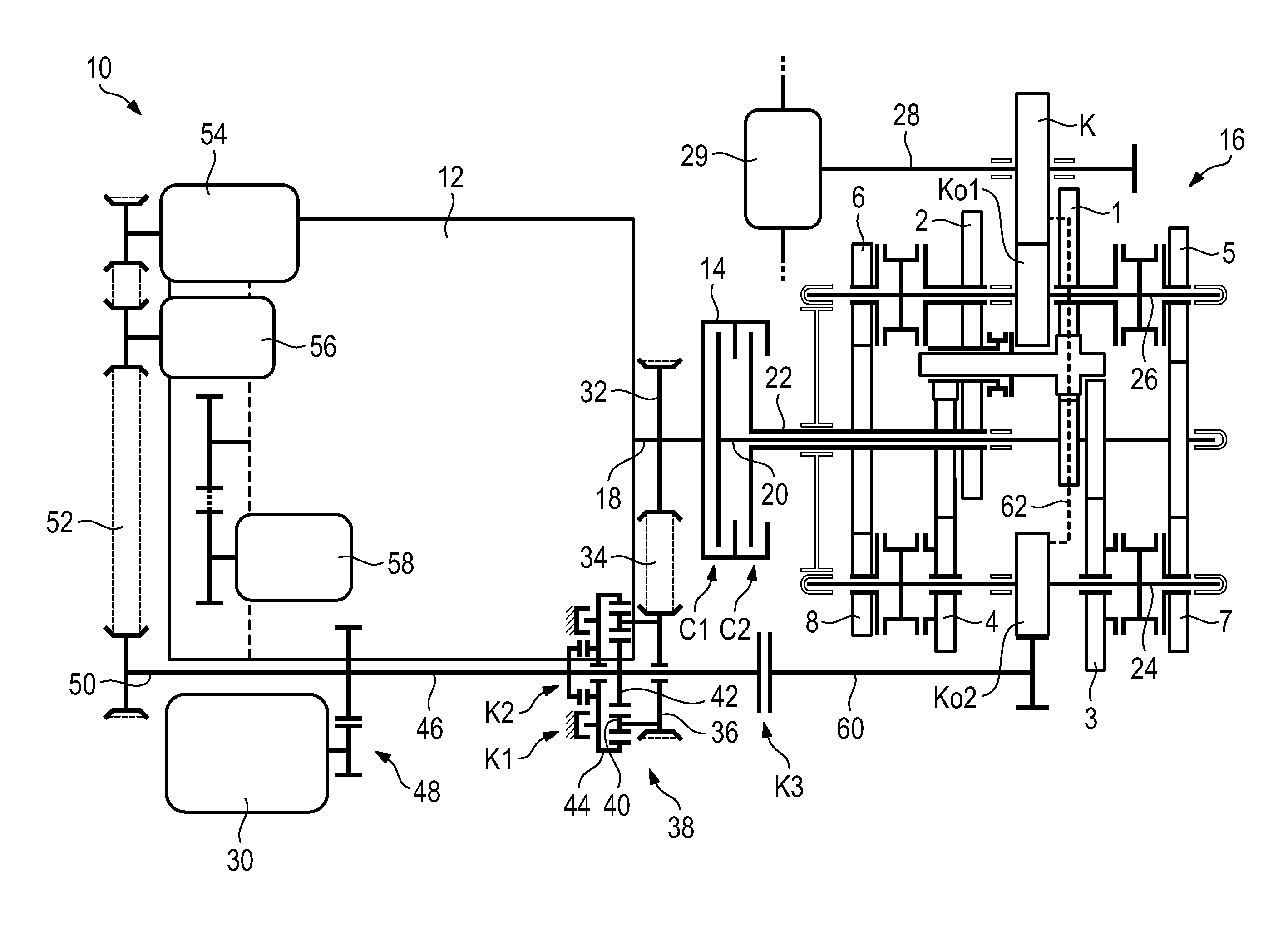
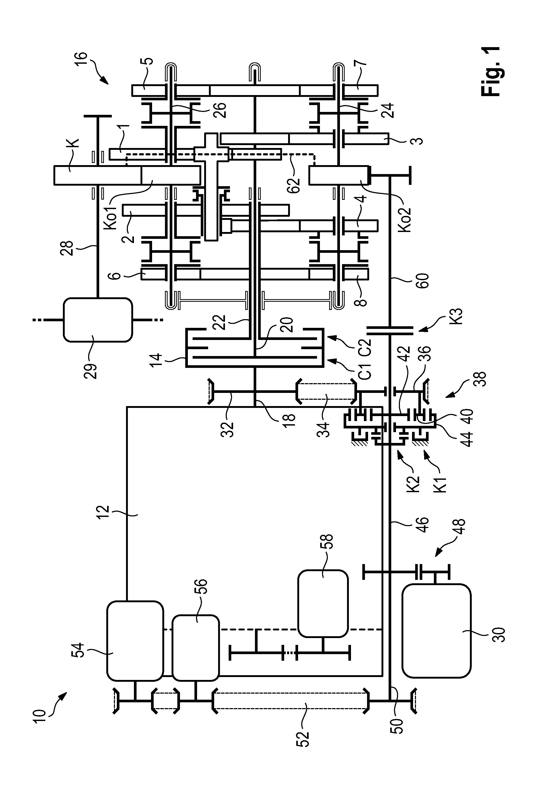
[0018]The drive train 10 shown in FIG. 1 for a hybrid motor vehicle has an internal combustion engine 12, which can be coupled to a motor vehicle transmission 16 by means of a transmission clutch 14 designed as a dual clutch. The transmission clutch 14 has a first component clutch C1 for coupling an engine shaft 18 of the internal combustion engine 12 to a first transmission input shaft 20 designed as a solid shaft, and a second component clutch C2 for coupling the engine shaft 18 to a second transmission input shaft designed as a hollow shaft. Within the motor vehicle transmission 16, the transmission input shafts 20, 22 mesh with a first selector shaft 24 for transmission gears 3, 4, 7 and 8 and with a second selector shaft 26 for transmission gears 1, 2, 5 and 6 via shiftable transmission stages. The second selector shaft 26 meshes via an output gearwheel Ko1 with an input gearwheel K of a transmission output shaft 28, which is coupled by a differential 29 to driven wheels (not s...


PUM


Abstract

The invention relates to a drive train (10) for a hybrid vehicle comprising an internal combustion engine (12) having a motor shaft (18) for providing a torque for driving the hybrid vehicle, and comprising an electric machine (30) for providing a torque for driving the hybrid vehicle, wherein the electric machine (30), in particular for starting of the internal combustion engine (12), can be coupled to the motor shaft (18) by means of a selectively engageable planetary gear unit (38) for providing at least two different transmission ratios, wherein the electric machine (30) can be coupled by means of a transmission gearing (48), in particular a sun gear system having a transmission ratio different from 1.0, having an intermediate shaft (46) for introducing the torque into the planetary gear unit (38).

Description

BACKGROUND[0001]1. Field of the Invention[0002]The invention relates to a drive train for a hybrid motor vehicle, with the aid of which a torque produced by an internal combustion engine and / or by an electric machine can be transmitted.[0003]2. Description of the Related Art[0004]US 2010 / 0216584 A1 discloses a drive train for a hybrid motor vehicle, in which an electric machine has a rotor, which is designed as an annulus of a planetary gearset. The annulus is coupled via planet wheels supported by a planet carrier to a sun wheel, which is connected for conjoint rotation to a transmission output shaft of a motor vehicle transmission to enable the hybrid motor vehicle to be driven electrically. The planet carrier is connected to a shaft connected via gearing to an engine shaft of an internal combustion engine in order to be able to start the internal combustion engine with the aid of the electric machine.[0005]There is a constant need to reduce the space required to install a drive t...

Claims


Application Information

Patent Timeline
IPC IPC(8): B60K6/365B60K6/26
CPCB60K6/26B60K6/365B60K2025/005B60K2006/268Y10S903/906Y10S903/91B60K6/48F16H3/006B60K2006/4808B60K2006/4825B60K2006/4841F16H2003/0931F16H2200/006Y02T10/62
Inventor MUELLER, STEPHANHEILFORT, FALKSCHULTIS, PHILIPP
Owner DR ING H C F PORSCHE AG
Why Eureka
Try Eureka