Flat-type heat pipe and wick structure thereof

Inactive Publication Date: 2012-11-08
CELSIA TECH TAIWAN INC
View PDF4 Cites 20 Cited by
  • Summary
  • Abstract
  • Description
  • Claims
  • Application Information

AI Technical Summary

Benefits of technology

[0018]The wick structure of the present invention comprises a first wick portion and two second wick portions connected on both sides of the first wick portion. The thickness of the first wick portion is larger than that of the second wick portion. The first wick portion abuts against an upper inner wall of the flat tube. Thus, the first wick portion is configured to support the upper inner wall of the flat tube. As a result, it is unnecessary to provide another additional supporting structure in the flat tube, so that the flat-type heat pipe can be made more compact. Since the inner walls of the flat tube are supported by the first wick portion, the flat tube will not be recessed due to the external atmospheric pressure.
[0019]Further, since the wick structure of the present invention comprises a first wick portion and two second wick portions

Problems solved by technology

However, according to the existing level in this art, the manufacture of thin heat pipes and super-thin heat pipes encounters problems as follows.
Thus, if a supporting structure is provided in the flat tube, the thickness of the supporting structure may inevitably increase the thickness of the thin heat pipe or the

Method used


Image

  • Flat-type heat pipe and wick structure thereof
  • Flat-type heat pipe and wick structure thereof
  • Flat-type heat pipe and wick structure thereof

Examples


Embodiment Construction

[0024]The detailed description and technical contents of the present invention will become apparent with the following detailed description accompanied with related drawings. It is noteworthy to point out that the drawings is provided for the illustration purpose only, but not intended for limiting the scope of the present invention.

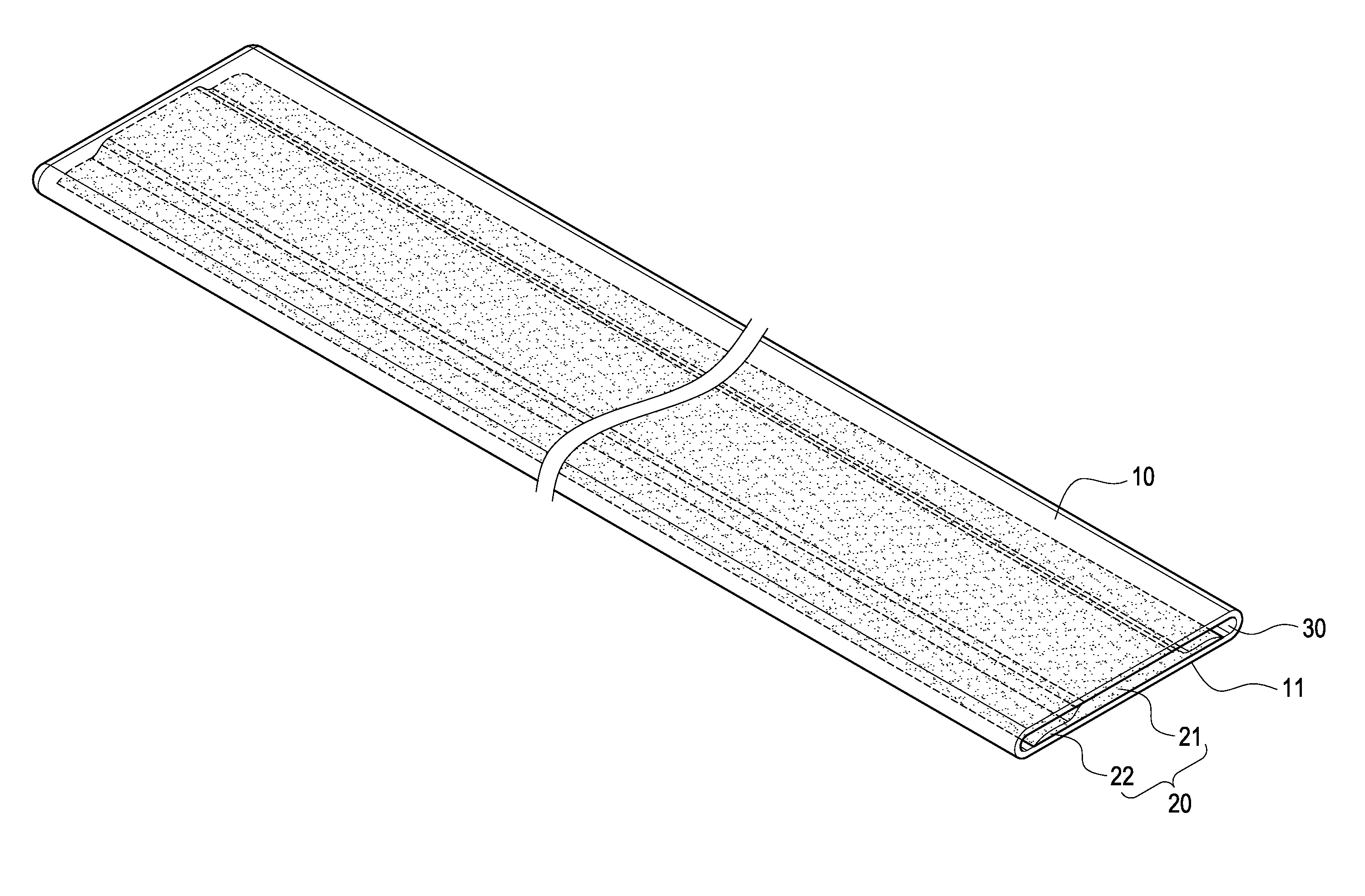
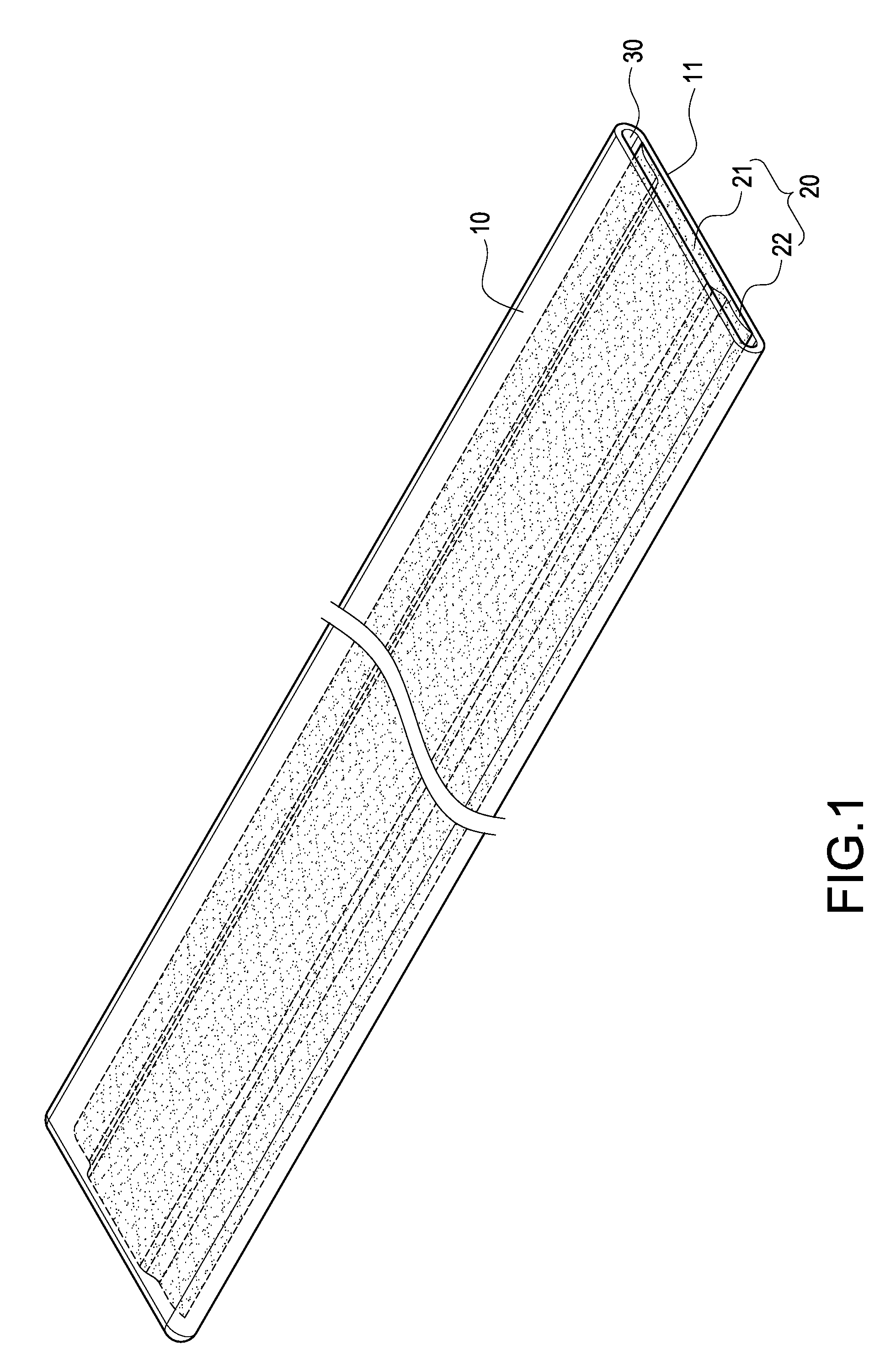
[0025]Please refer to FIGS. 1 to 3. The present invention provides a wick structure of a flat-type heat pipe. The flat-type heat pipe 1 has a flat tube 10. The wick structure 20 is arranged inside the flat tube 10 along an axial line of the flat tube 10. The wick structure 20 is made by sintered metal powder.

[0026]The manufacturing procedure of the present invention will be described as follows.

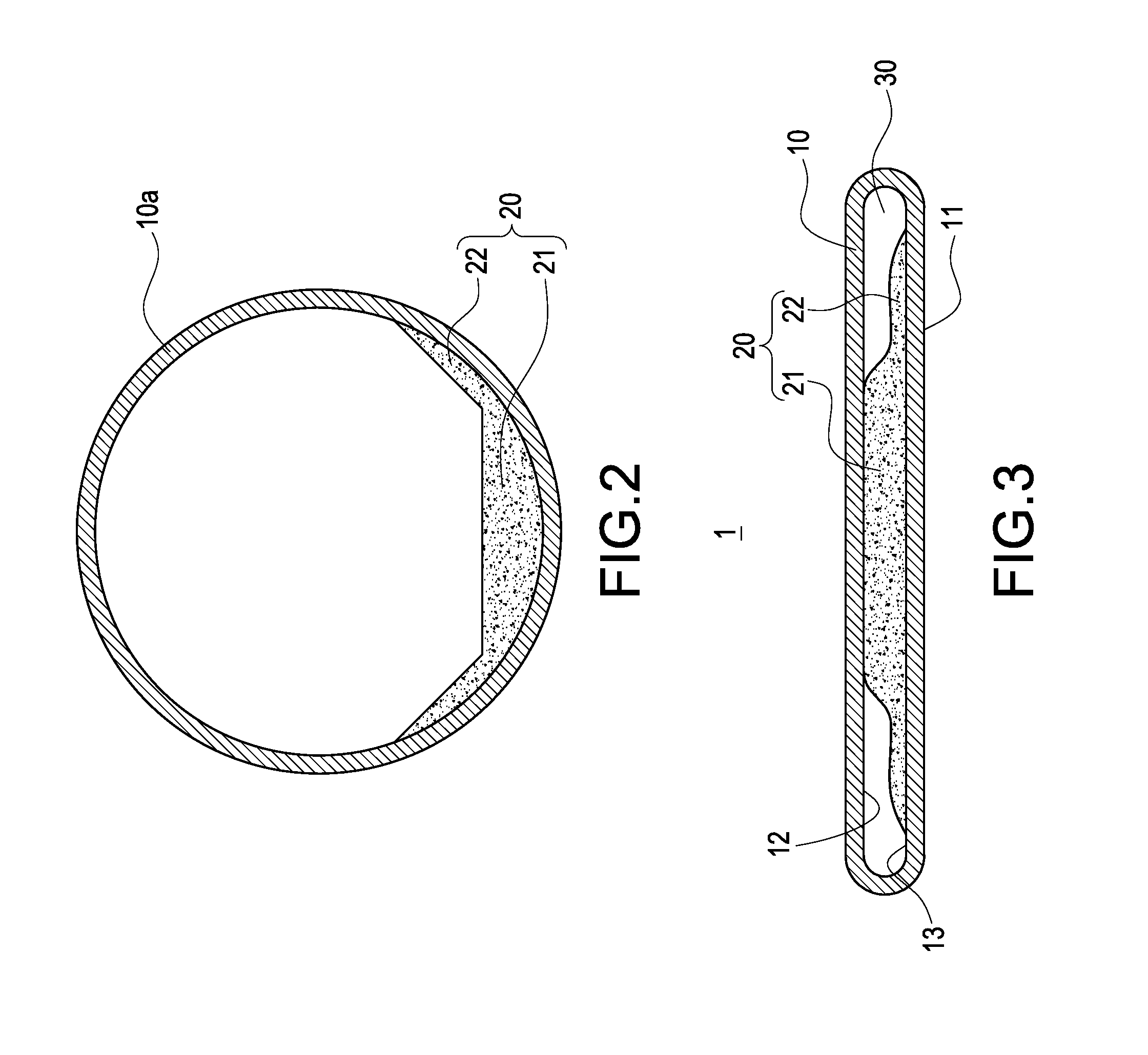
[0027]First, a circular tube 10a is provided, which has smooth inner walls. Then, a core rod (not shown) is inserted into the circular tube 10a. The outer diameter of the core rod is smaller than the inner diameter of the circular tube 10a. The profile of the uppe...


PUM


Abstract

The present invention provides a flat-type heat pipe and a wick structure thereof. The flat-type heat pipe has a flat tube. The wick structure is arranged inside the flat tube along an axial line of the flat tube. The wick structure comprises a first wick portion and two second wick portions connected on both sides of the first wick portion. The thickness of the first wick portion is larger than that of the second wick portion. The first wick portion abuts against an upper inner wall of the flat tube. An air channel is formed between each of the second wick portions and the upper inner wall of the flat tube. The wick structure supports the inner wall of the flat-type heat pipe without providing additional supporting structure, so that the heat pipe can be made more compact.

Description

BACKGROUND OF THE INVENTION[0001]1. Field of the Invention[0002]The present invention relates to a heat pipe, in particular to a flat-type heat pipe and a wick structure thereof.[0003]2. Description of Prior Art[0004]With the advancement of science and technology, electronic products and electronic elements are made more and more compact. Thus, heat pipes associated with these compact electronic products and electronic elements have to be made compact accordingly. According to the existing level in this art, a heat pipe whose thickness is smaller than 2 mm is referred to as a “super-thin heat pipe”, and a heat pipe whose thickness is larger than 2 mm is referred to as a “thin heat pipe”.[0005]However, according to the existing level in this art, the manufacture of thin heat pipes and super-thin heat pipes encounters problems as follows. Since the thin heat pipe or the super-thin heat pipe has a flat tube, the thickness of the flat tube is required to be small enough to manufacture a...

Claims


Application Information

Patent Timeline
IPC IPC(8): F28D15/04
CPCF28D15/046
Inventor MEYER, IV, GEORGE ANTHONYSUN, CHIEN-HUNGCHEN, CHIEH-PINGCHIN, TE-HSUAN
Owner CELSIA TECH TAIWAN INC
Why Eureka
Try Eureka