Contacts of board-to-board connector

a technology of contact and connector, which is applied in the direction of coupling contact members, fixed connections, coupling device connections, etc., can solve the problems of unfavorable recent downsizing trends and the height of the entire connector assembly after engagement, and achieve the effects of increasing positive pressure, increasing thickness, and increasing for

a technology of contact and connector, which is applied in the direction of coupling contact members, fixed connections, coupling device connections, etc., can solve the problems of unfavorable recent downsizing trends and the height of the entire connector assembly after engagement, and achieve the effects of increasing positive pressure, increasing thickness, and increasing for

US20060178022A1Inactive Publication Date: 2006-08-10MOLEX INC

Image

  • Contacts of board-to-board connector
  • Contacts of board-to-board connector
  • Contacts of board-to-board connector

Examples


Embodiment Construction

[0024] To provide a clear understanding of the present invention, a detailed description of a preferred embodiment of the present invention with reference to the accompanying drawings is provided as follows.

[0025] As shown in FIGS. 4, 5 and 8, an electrical connector assembly 10 of the present invention is a board-to-board electrical connector including a socket connector 20 and a plug connector 30 respectively mounted on each circuit board (not shown) to accomplish the electrical connection between the two circuit boards by the engagement of the socket connector 20 and the plug connector 30.

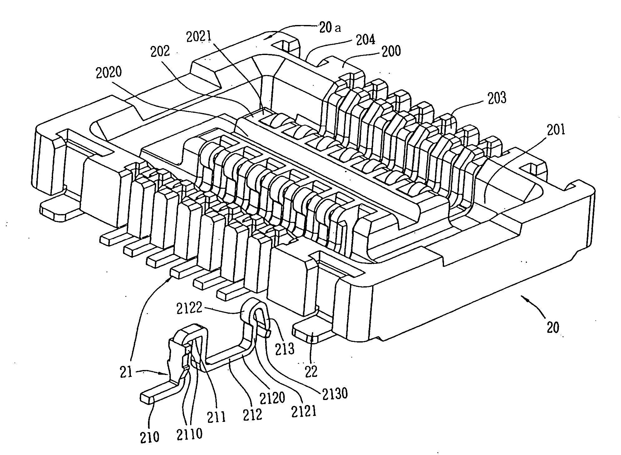
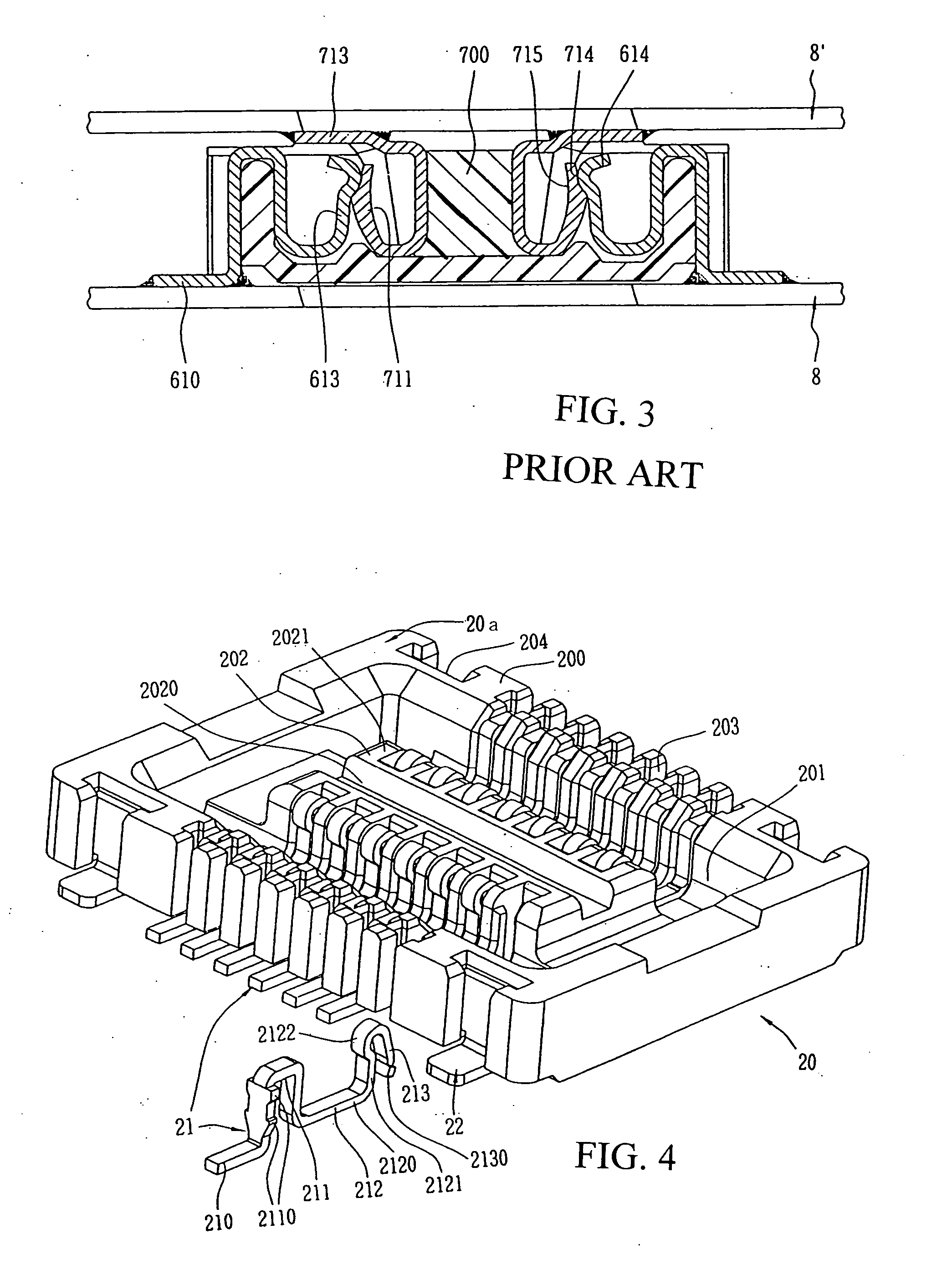
[0026] As shown in FIGS. 4, 6a and 6b, the socket connector 20 of the electrical connector assembly 10 includes a rectangular insulating socket base 20a, a plurality of first terminals 21 mounted in parallel to the insulating base 20a, and two pairs of auxiliary-soldering tabs 22 mounted to the insulating socket base 20a to evenly fix the socket connector 20 to a circuit board.

[0027] Two firs...


PUM


Abstract

An electrical connector assembly includes a socket connector soldered on one circuit board and a plug connector soldered on another circuit board. The socket connector includes an insulating socket base and a plurality of first terminals received in the first terminal-receiving slots of the insulating socket base. Each first terminal successively extends to form a first terminal lead, a first inverted U-shaped portion, a base U-shaped portion and an auxiliary-clamping portion. One leg of the base U-shaped portion includes a first elastic-contact portion. The plug connector includes an insulating plug base and a plurality of second terminals received in the second terminal-receiving slots of the insulating plug base. Each second terminal successively extends to form a second terminal lead and a second inverted U-shaped portion having a second elastic-contact portion. The second inverted U-shaped portion of the second terminal is inserted into the base U-shaped portion of the first terminal, and the first elastic-contact portion contacts the second elastic-contact portion when mating. The invention can provide stable mating and electrical connection and is in compliance with recent downsizing trends.

Description

FIELD OF THE PRESENT INVENTION [0001] The present invention relates to an electrical connector assembly, more specifically to a low profile board-to-board connector for transferring high-speed communication signals. DESCRIPTION OF RELATED ART [0002] U.S. Pat. No. 5,975,916 discloses an electrical connector assembly including a socket and a plug whose surfaces are respectively mounted on two corresponding circuit board to interconnect the two circuit boards. This reference as shown in FIG. 1 herein, discloses a socket 6 of the electrical connector assembly which includes a rectangular dielectric socket base 60 and a plurality of first terminals 61 parallel mounted in the socket base 60. Two banks 600 project from two sides along the length of the socket base 60 to define a recess 601 between the banks. Each bank 600 comprises a plurality of vertical terminal-receiving slots 602 with evenly spaced openings for securing the first terminals 61. A rib 603 integrally molded with the socke...

Claims


Application Information

Patent Timeline
10 Aug 2006
Publication
US20060178022A1
IPC
H01R12/00; H01R12/57
CPC
H01R13/26; H01R23/68; H01R12/52; H01R12/716
Inventors
LIU, JUN-XIAN