
Return pad cable connector

a technology of return pad and connector, which is applied in the direction of medical/surgical connector, sensor, heating instrument, etc., can solve the problems of broken wire strands or wires that cannot be formed or terminated properly in subsequent operations, the existing terminating and connection manufacturing process is overly complex, and the impedance change across the tissue is typically difficult to achieve, so as to facilitate the electrical connection

Inactive Publication Date: 2007-02-27
COVIDIEN AG
View PDF113 Cites 68 Cited by
  • Summary
  • Abstract
  • Description
  • Claims
  • Application Information

AI Technical Summary

Benefits of technology

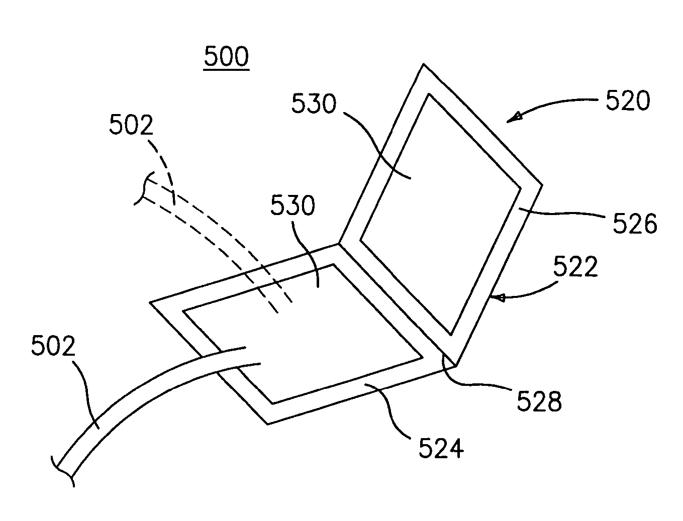
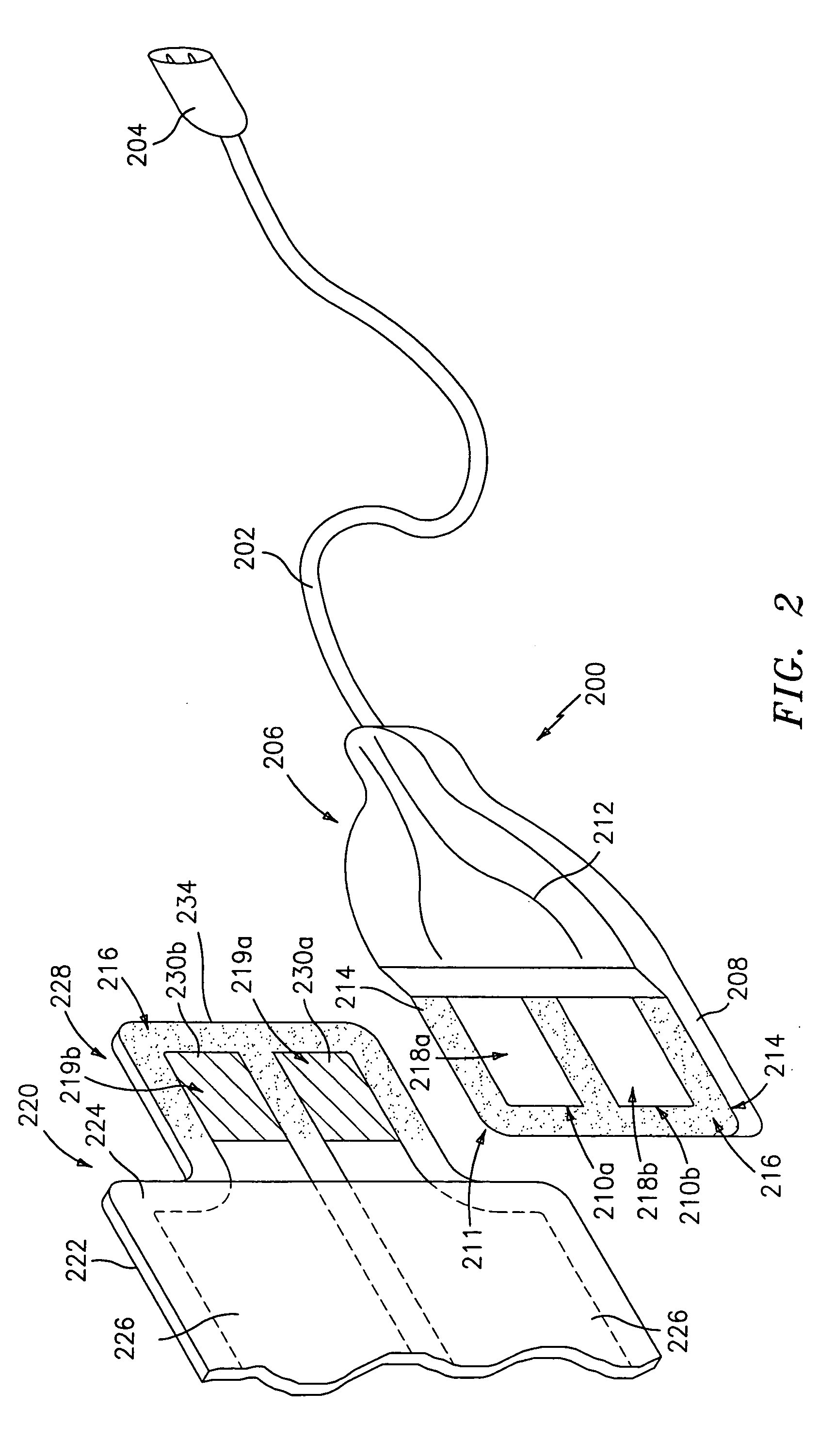
The present disclosure is about a return pad cable connector for use with a disposable return pad in electrosurgical procedures. The connector has a conductive wire that connects to an electrosurgical energy source and a connector that is attached to the wire and has a conductive surface that engages with a conductive surface on the return pad. The connector can be locked in a closed position to securely connect the wire to the return pad. The return pad cable connector can also include a magnet that magnetically attaches the connector to the return pad, allowing for energy transfer. The technical effects of this invention include improved safety and efficiency in electrosurgical procedures.

Problems solved by technology

Wire stripping problems can result in broken wire strands or wires that cannot be formed or terminated properly in subsequent operations.
As can be appreciated, existing terminating and connection manufacturing processes tend to be overly complex and typically require tedious manufacturing steps to assure adequate electrical and mechanical connections.
Inadequate electrical connections can result in impedance changes across the tissue which may effect the performance of the overall electrosurgical system.
Disposal of both the return pad and the conductive portion simply increases the costs associated with the medical procedure.

Method used


Image

  • Return pad cable connector
  • Return pad cable connector
  • Return pad cable connector

Examples


Embodiment Construction

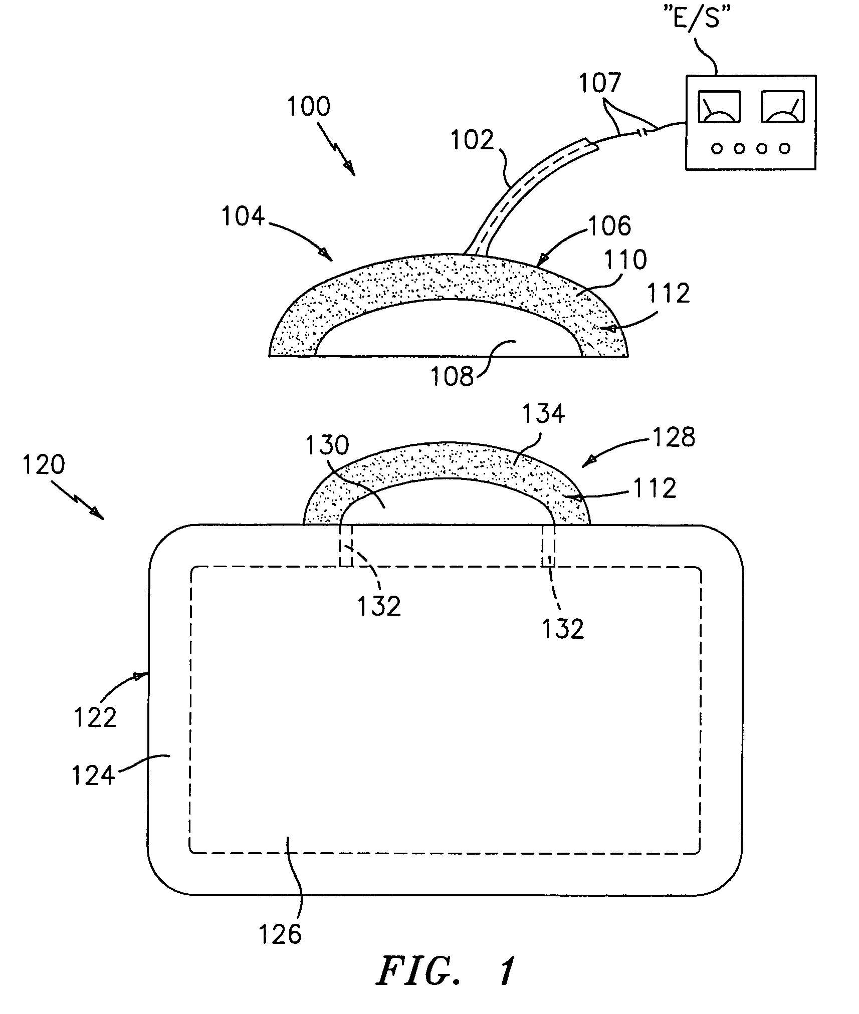
[0033]Preferred embodiments of the presently disclosed return pad cable connector will now be described in detail with reference to the drawing figures wherein like reference numerals identify similar or identical elements.

[0034]Referring now in detail to FIG. 1, a return pad cable connector is shown in accordance with the present disclosure and is generally identified as 100. Cable connector 100 includes a reusable conductive wire cable 102 which operatively couples at a proximal end thereof to an electrosurgical generator “E / S” and a reusable cord-to-pad interface 104 which is disposed at a distal end thereof. Cord-to-pad interface 104 includes an insulated backing 106 having a conductive cord surface 108 disposed thereon which electrically couples to a wire 107 passing through cable 102.

[0035]An adhesive border 110 is defined about the outer periphery of the conductive cord surface 108. It is contemplated that conductive cord surface 108 may be positioned along one edge of cord-t...


PUM


Abstract

A return pad cable connector, in accordance with the present disclosure, for use with a disposable return pad, includes a cord having a conductive wire disposed therethrough which conductive wire interconnects the return pad cable connector to an electrosurgical energy source. The return pad further includes a connector operatively coupled to the cord, the connector having a conductive surface which is selectively engageable with a corresponding conductive surface disposed on the return pad, the conductive surface of the connector including a conductive adhesive disposed thereon and a non-conductive adhesive disposed above the periphery of the conductive surface of the connector for engagement with a corresponding non-conductive adhesive disposed above the periphery of the conductive surface of the return pad. The connector can include a magnet for magnetically coupling the connector to the conductive surface disposed on the return pad.

Description

BACKGROUND[0001]1. Technical Field[0002]The present disclosure relates to a return pad cable connector and, more particularly, to a return pad cable connector having a reusable cable configuration and adapted to removably receive a disposable single use patient return pad.[0003]2. Background of Related Art[0004]Flexible conductive members (i.e., return pads, return electrodes, etc.) are of particular importance in the medical community wherein patients often need to be connected to electrical monitoring or electrical generating equipment. In such applications, flexible conductive members such as return pads or electrodes need to adapt to the shape of the patient's body in order to provide sufficient electrical contact with the surface of the patient's body.[0005]Electrosurgery requires that an electrosurgical generator be connected to at least two electrodes to produce and deliver an electrical potential to a patient's body. For example, in monopolar electrosurgery, the electrodes u...

Claims


Application Information

Patent Timeline
Patent Type & Authority Patents(United States)
IPC IPC(8): H01R11/30A61B5/274A61B17/00A61B18/00A61B18/14A61B18/16A61N1/04H01R4/04H01R4/26H01R11/22H01R13/62
CPCA61B18/14A61B18/16A61N1/048H01R11/22H01R13/6205H01R4/04A61B2017/00477A61B2018/00178A61B2018/00988Y10S128/908H01R4/26H01R2201/12Y10S439/909
Inventor EHR, CHRIS J.SCHOENMAN, ARTHUR
Owner COVIDIEN AG
Learn More