Piezoelectric vibrator

a technology piezoelectric, which is applied in the direction of mechanical vibration separation, generator/motor, instruments, etc., can solve the problems of structural damage, excessive stress applied to piezoelectric vibrating plate, and destruction of piezoelectric elements made of fragile materials, etc., to improve the mountability and reliability of piezoelectric vibrating plate, and excellent shock resistance

Inactive Publication Date: 2005-02-03
TAIYO YUDEN KK
View PDF2 Cites 78 Cited by
  • Summary
  • Abstract
  • Description
  • Claims
  • Application Information

AI Technical Summary

Benefits of technology

In view of the foregoing, in an embodiment, an object of the present invention is to provide a piezoelectric vibrator having ex

Problems solved by technology

However, the conventional device described so far has the following problems.
(1) When an impact load is applied to the piezoelectric vibrating body, an excessive stress is applied to the piezoelectric vibrating plates.
This may destroy the piezoelectric elements made of a fragile material, or they may come off the pillar or the vibrating plates may bend.
In this way, structural damage occurs.
Concomitantly with this, there arises the danger that the circuit is affected.
Furthermore, where plural piezoelectric vibrating plates are used, contact between any pie

Method used


Image

  • Piezoelectric vibrator
  • Piezoelectric vibrator
  • Piezoelectric vibrator

Examples


embodiment 1

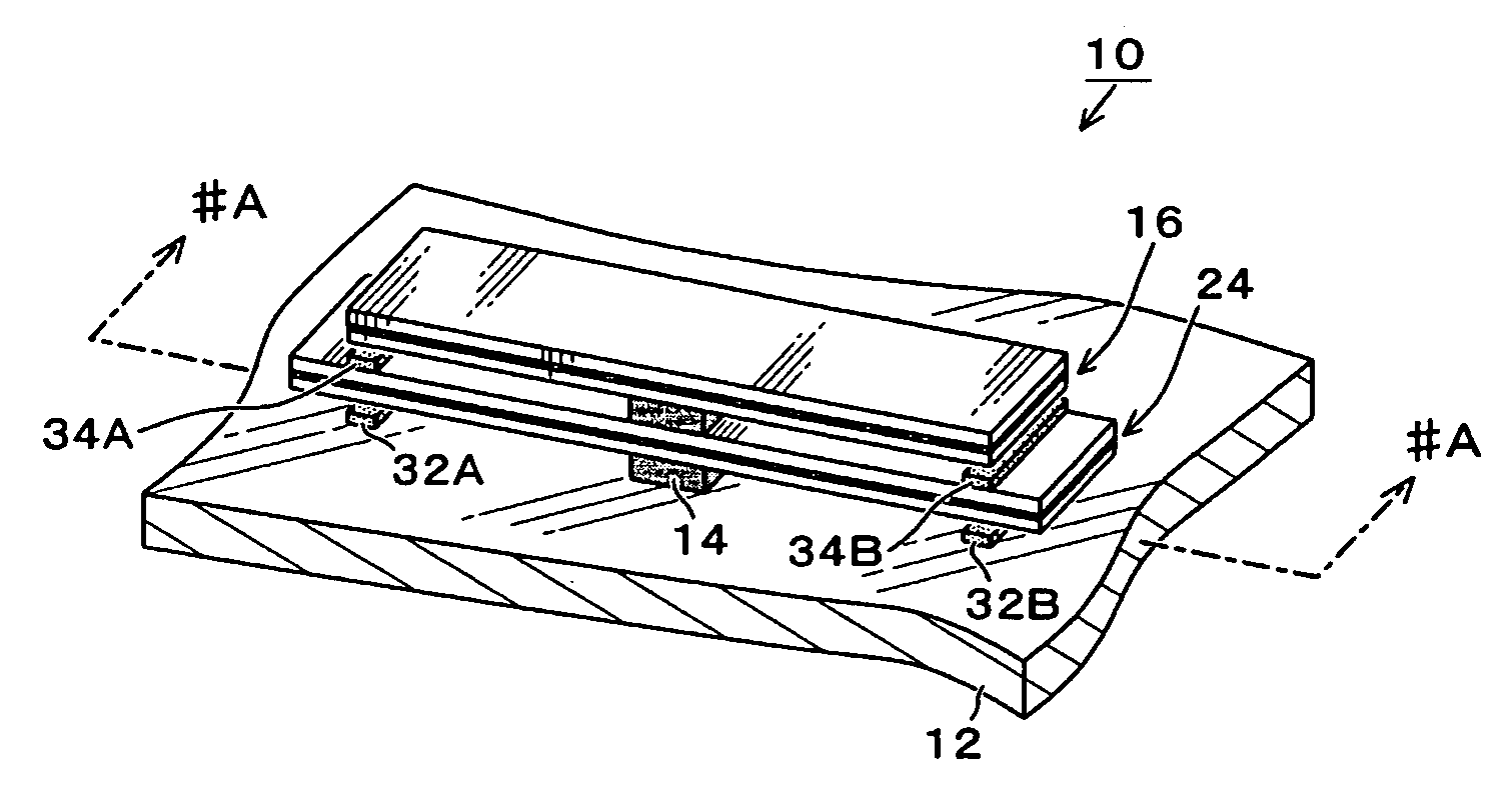
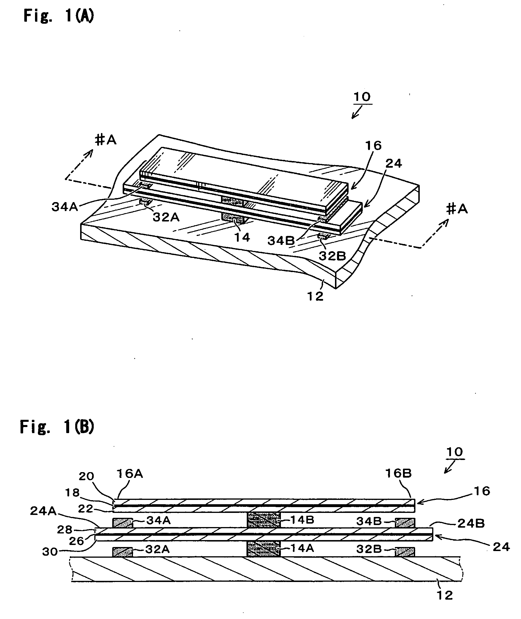
Embodiment 1 of the present invention is first described with reference to FIGS. 1A and 1B. FIG. 1A is a perspective view showing the outer appearance of the present embodiment. FIG. 1B is a cross-sectional view showing the state obtained when a cross section taken along line #A-#A of FIG. 1A is viewed in the direction of the arrows.

As shown in the figures, a piezoelectric vibrator 10 of the present embodiment has substantially rectangular piezoelectric vibrating plates 16 and 24. Nearly central portions of the plates 16 and 24 are mounted to one main surface of the enclosure or case 12 of a mobile phone or the like by pillars 14A and 14B so as to be substantially parallel to the enclosure 12. The piezoelectric vibrating plates 16, 24 and pillars 14A, 14B are stacked in the order—enclosure 12, pillar 14A, piezoelectric vibrating plate 24, pillar 14B, and piezoelectric vibrating plate 16. They are fastened with adhesive or the like. This lamination may be held from above with a ma...

embodiment 2

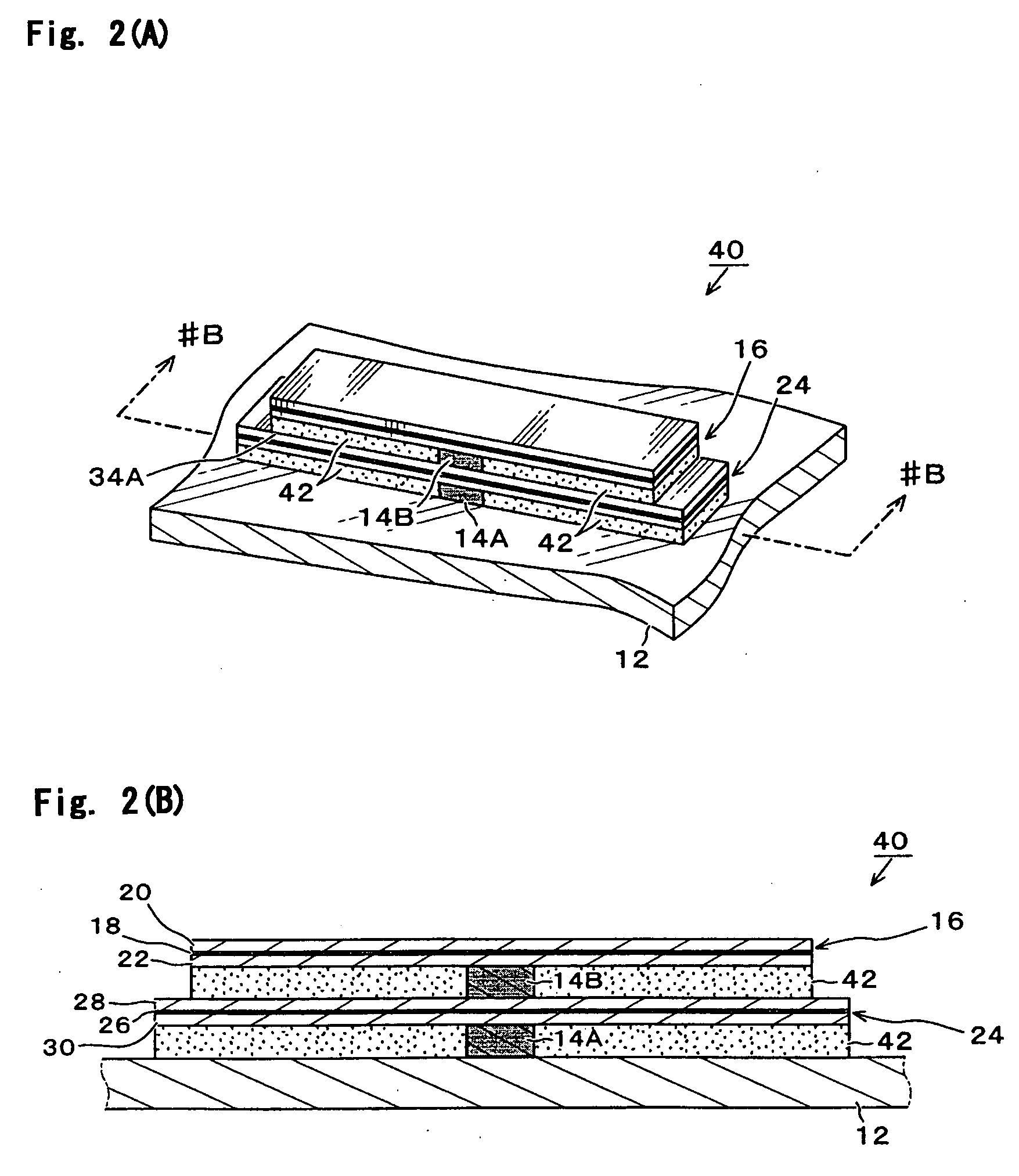
Embodiment 2 of the present invention is next described with reference to FIGS. 2A and 2B. FIG. 2A is a perspective view showing the structure of the present embodiment. FIG. 2B shows a cross section taken along line #B-#B of FIG. 2A, as viewed in the direction of the arrows. Identical symbols are used for the components which are identical or correspond to those of the above-described embodiment (the same convention applies to the following embodiments).

As shown in FIGS. 2A and 2B, a piezoelectric vibrator 40 of the present embodiment is fundamentally identical in structure with the above-described embodiment. Piezoelectric vibrating plates 16 and 24 are mounted on a main surface of an enclosure 12 by pillars 14A and 14B so as to be substantially parallel. The space between the main surface of the enclosure 12 and piezoelectric vibrating plate 24 and the space between the piezoelectric vibrating plates 16 and 24 are filled with a flexible resilient material 42. Vibration of the ...

embodiment 3

Embodiment 3 of the present invention is next described with reference to FIGS. 3A and 3B. FIG. 3A is a perspective view showing the configuration of the present embodiment. FIG. 3B is a cross-sectional view taken along line #C-#C of FIG. 3A, as viewed in the direction of the arrows. In all of the above-described Embodiments 1 and 2, nearly centers of the substantially rectangular piezoelectric vibrating plates 16 and 24 are supported by the pillars 14A and 14B. In the present embodiment, both ends of the piezoelectric vibrating plates 16 and 24 are held by pillars.

As shown in FIG. 3, a piezoelectric vibrator 50 of the present embodiment is so constructed that both ends of the piezoelectric vibrating plates 16 and 24 are supported by pillars 52 and 54 such that the piezoelectric vibrating plates 16 and 24 are substantially parallel to the main surface of an enclosure 12. The piezoelectric vibrating plate 16 is placed on steps 52A and 54A formed above the pillars 52 and 54. The pi...


PUM


Abstract

A piezoelectric vibrator having excellent shock resistance and high reliability is offered. The centers of first and second piezoelectric vibrating plates are supported by pillars on a main surface of an enclosure and nearly or substantially parallel to the main surface of the enclosure. Spacers having a Young's modulus of less than 2 GPa are mounted on both end sides of the second piezoelectric vibrating plate to prevent contact between the vibrating plates, thus preventing damage. Other spacers are mounted on the main surface of the enclosure in positions corresponding to the first-mentioned spacers to prevent contact with the main surface of the enclosure, thus preventing damage to the second piezoelectric vibrating plate.

Description

BACKGROUND OF THE INVENTION This is a U.S. patent application claiming foreign priority under 35 U.S.C. § 119 to Japanese Patent Application No. 2003-279478, filed Jul. 24, 2003, the disclosure of which is herein incorporated by reference in their entirety. 1. Field of the Invention The present invention relates to a piezoelectric vibrator used in an acoustic transducing electronic appliance (such as an enclosure vibration type flat speaker or receiver) or in a vibration transducing electronic appliance such as a vibrator. More particularly, the invention relates to a piezoelectric vibrator having improvements in shock resistance, mountability, and reliability. 2. Description of the Related Art Piezoelectric vibrators utilizing piezoelectric elements are widely employed as simple electro-acoustic transducers and actuators. Especially, in recent years, they are often used in the field of mobile phones, personal digital assistants, and so on. A conventional piezoelectric vibrator...

Claims


Application Information

Patent Timeline
IPC IPC(8): H04R17/00B06B1/04B06B1/06G10K11/00H01L41/053H04R1/00H04R1/02H04R7/04
CPCB06B1/0611H04R1/00H04R17/00H04R31/003
Inventor SASHIDA, NORIKAZUITOH, HUMIHISAISHII, SHIGEOWATANABE, YOSHIYUKI
Owner TAIYO YUDEN KK
Why Eureka
Try Eureka