Plastering composite wall with reinforcing steel bar and/or metal net equipped at inter and outer or two-side

A composite wall and external metal mesh technology, applied in the field of building composite walls, can solve the problems of incomplete connection structure, troublesome construction and high cost, and achieve the effects of reducing horizontal seismic action, high safety and reducing damage.

Inactive Publication Date: 2008-04-30
吴淑环
View PDF1 Cites 53 Cited by
  • Summary
  • Abstract
  • Description
  • Claims
  • Application Information

AI Technical Summary

Problems solved by technology

[0005] The purpose of the present invention is to provide a composite wall with steel bars and / or metal mesh plastering on the inside and outside or on both sides. The connection structure of the bundled composite thermal insulation wall with support is not comprehensive, and it is not suitable for some heat insulation requirements. High areas may have problems of troublesome construction and high cost. Therefore, the composite wall with multiple connection structures is proposed, which is more convenient for construction, greatly reduces the cost of composite walls, and more widely satisfies different areas, different buildings, and different structures. Requirements

Method used


Image

  • Plastering composite wall with reinforcing steel bar and/or metal net equipped at inter and outer or two-side
  • Plastering composite wall with reinforcing steel bar and/or metal net equipped at inter and outer or two-side
  • Plastering composite wall with reinforcing steel bar and/or metal net equipped at inter and outer or two-side

Examples


specific Embodiment approach 1

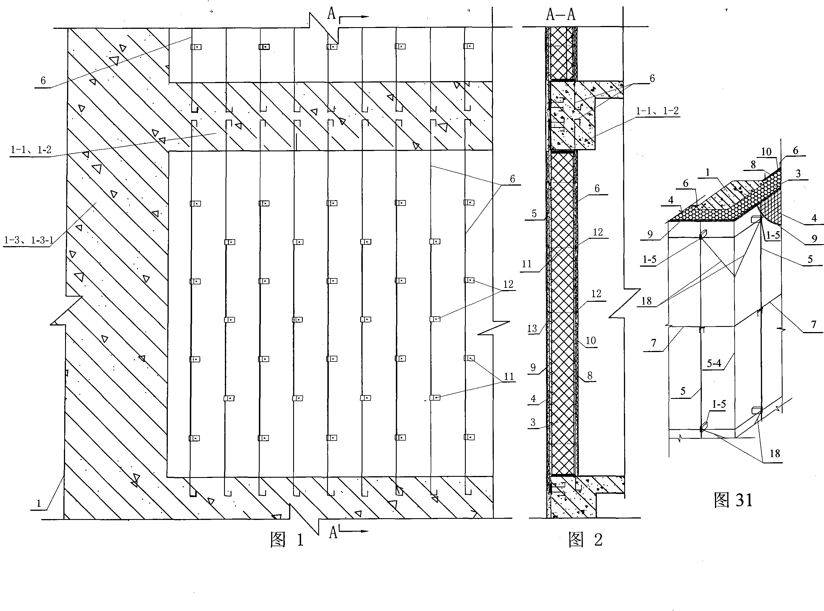
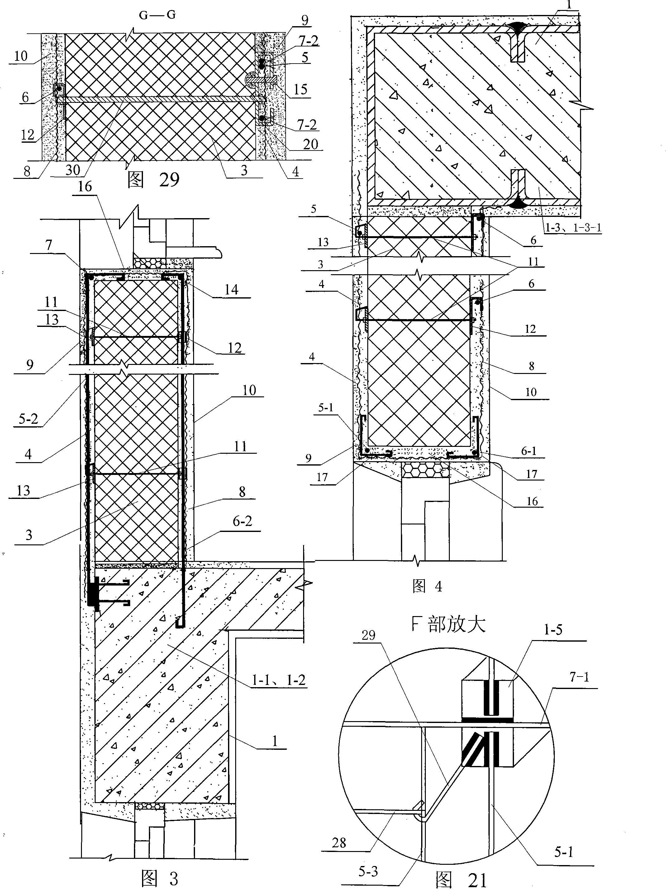
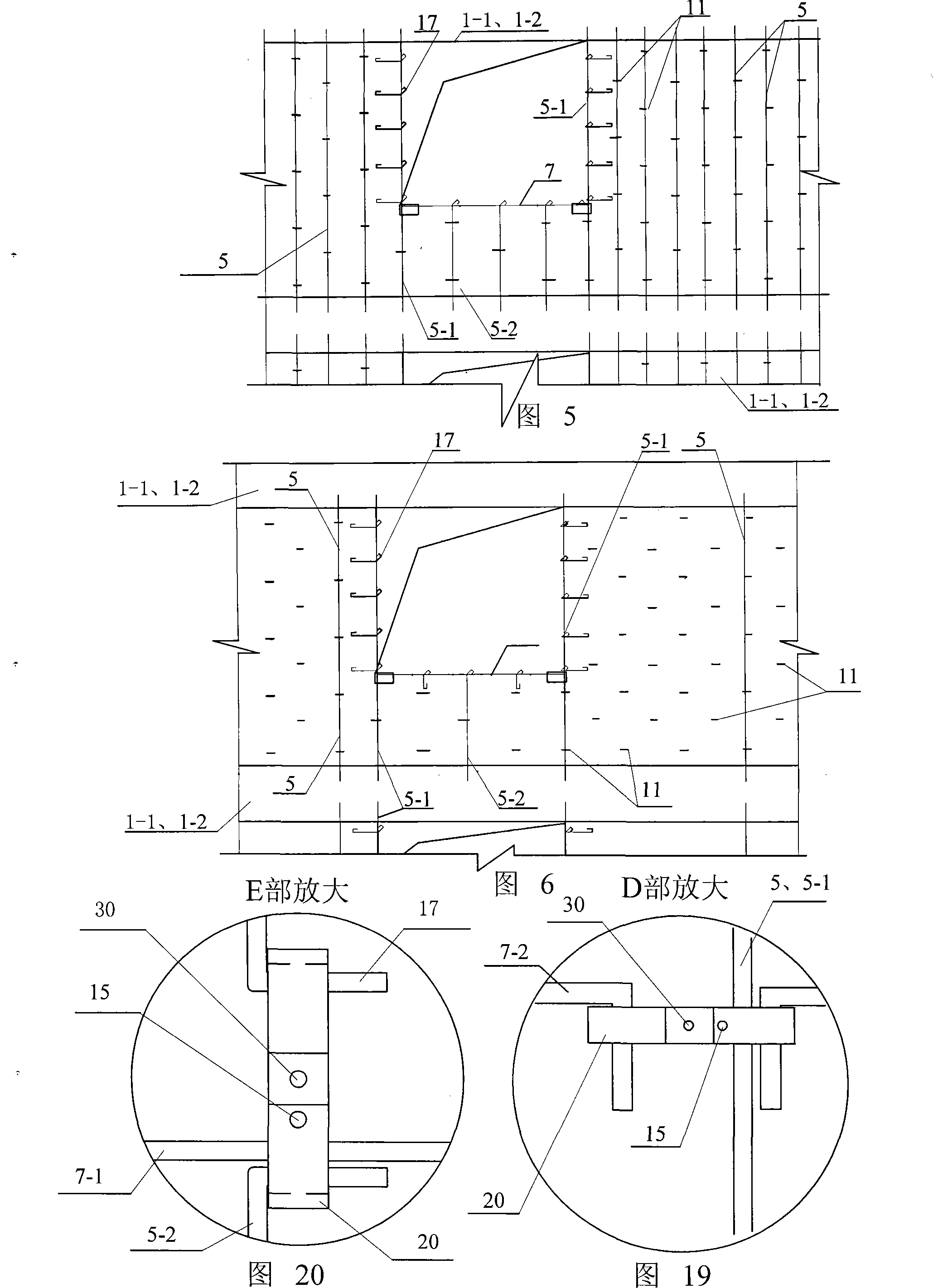
[0009] Specific Embodiment 1: The embodiment is described with reference to FIGS. 1 to 6. A structure of a composite wall in this embodiment consists of a load-bearing member 1 of the main structure of the building, a core layer 3, an outdoor vertical steel bar 5, and vertical vertical bars on the side edges of outdoor doors and windows. Directional reinforcement 5-1, vertical reinforcement below the outdoor window sill 5-2, indoor vertical reinforcement 6, indoor door and window side edge vertical reinforcement 6-1, indoor vertical reinforcement 6-2 under the window sill, outdoor horizontal horizontal reinforcement 7, and indoor window sill horizontal Steel bars 14, outer protective layer 9, inner protective layer 10, and opening protective layer 16; the load-bearing member 1 of the main structure of the building is a beam 1-1, a cantilevered plate 1-2, a column 1-3 or a short limb shear force Wall 1-3-1; the upper and lower ends of the outdoor vertical steel bar 5, the vertic...

specific Embodiment approach 2

[0011] Specific embodiment 2: This embodiment is described with reference to FIGS. Two steel gaskets 13; the first steel gasket 12 has a hook fixed on the indoor vertical reinforcement 6, the vertical reinforcement 6-2 under the indoor window sill and the vertical reinforcement 6-1 at the side edge of the indoor door and window, the core layer 3 and the second A steel gasket 12 is attached, and one end of the steel wire 11 is connected from the inside to the outside in turn through the first steel gasket 12, the core layer 3 and the second steel gasket 13. The outer end of the steel wire 11 is bent and fixedly connected with the outdoor vertical steel bar 5, the vertical steel bar 5-2 under the outdoor window sill and the vertical steel bar 5-1 at the side edge of the outdoor door and window. When the core layer 3 is a polymer insulation board, it is advisable to adopt this embodiment. The internal and external drawing and connecting steel wire 11 can be used for M3 stainless ...

specific Embodiment approach 3

[0012] Specific embodiment three: This embodiment is described in conjunction with Fig. 1 to Fig. 6. The difference between this embodiment and specific embodiment two is: this embodiment also adds an outdoor metal mesh 4; the outdoor metal mesh 4 is located at the outdoor vertical steel bar 5 1. The vertical steel bar 5-1 on the side edge of the outdoor door and window, the inner side or the outer side of the vertical steel bar 5-2 under the outdoor window sill and fastened, and the outer end of the steel wire 11 connected inside and outside is bent and hooked to the outdoor vertical steel bar 5, under the outdoor window sill The vertical reinforcement 5-2 and / or the outer end of the internal and external tensioning steel wire 11 is bent and hooked to the outdoor metal mesh 4 for fastening connection, and the outdoor metal mesh 4 is horizontally connected to the outdoor window sill at the door and window opening. Bind and connect to steel bar 5-1, and bend it into the room to ...


PUM


Abstract

The utility model relates to a compound wall with reinforcing bars and / or metal mesh plastering on the inside and outside or on both sides, which relates to a building compound wall. Aiming at the incomplete structure of the bundled composite thermal insulation wall with support. Option 1: Outdoor vertical steel bars (5) and indoor vertical steel bars (6) are fixed to the outside and inside of the load-bearing member (1) of the main building structure, and the inner and outer sides of the core layer (3) are provided with inner and outer protection plan 2: the vertical steel bar (5-2) under the outdoor window sill and the vertical steel bar (6-2) under the indoor window sill are fixed to the cantilever plate (1-2); plan 3: indoor The vertical reinforcement (6) is fixed to the indoor floor of the load-bearing member (1) of the main structure of the building; scheme 4: the indoor vertical reinforcement (6) on both sides of the air layer, and the inner and outer sides of the indoor metal mesh are provided with protective layers (10 -1), the air layer (3-1) is located between the protective layers (10-1) on both sides. The invention has the advantages of good earthquake resistance, good wind load resistance, low cost, convenient construction, good safety of the outer decorative surface layer, increased indoor usable area, and meets the requirements of low energy consumption buildings.

Description

technical field [0001] The invention relates to a building composite wall. Background technique [0002] For thousands of years, human society has used brittle materials such as stones, bricks, blocks, and concrete as walls except for wooden structures. In the world, the population is increasing rapidly, there are more and more high-rise buildings, and people are demanding higher and higher levels of comfort. Today, with energy shortages and serious environmental pollution, these traditional walls have highlighted the shortcomings of poor thermal insulation, energy saving, and poor earthquake resistance, and firing red bricks consumes a lot of arable land. [0003] The exterior walls of buildings in heating areas are like our cotton-padded clothes in winter, and the exterior walls of buildings in hot summer areas are like the shell of refrigerators. In order to save energy in buildings, in the past 30 years, Europe and the United States have successively studied and applied...

Claims


Application Information

Patent Timeline
Patent Type & Authority Applications(China)
IPC IPC(8): E04B1/76E04B2/00E04B1/00E04F13/00
Inventor 吴淑环
Owner 吴淑环
Why Eureka
Try Eureka