Vibration isolation device

a technology of vibration isolation and plastic brackets, which is applied in the direction of shock absorbers, machine supports, other domestic objects, etc., can solve the problems of inability to ensure the reliability of the press-fit engagement between the plastic bracket and the metal cap, the plastic bracket may be damaged or broken, and the cost of man-hours is increased

Active Publication Date: 2007-11-13
HONDA MOTOR CO LTD +1
View PDF32 Cites 50 Cited by
  • Summary
  • Abstract
  • Description
  • Claims
  • Application Information

AI Technical Summary

Benefits of technology

[0009]It is, therefore, an object of the present invention to provide a vibration isolation device which is lightweight, can be assembled through a press-fitting operation used for assembling a subassembly including an elastic member relative to a bracket adapted to be attached to a vibratory source or a support body, and is able to protect a plastic bracket against damage or rupturing which may occur during press-fitting operation.
[0011]With this arrangement, the plastic bracket used for attachment to the vibratory source or the support body can achieve a certain reduction of the overall weight of the vibration isolation device. Furthermore, by virtue of the elastic member disposed between the non-engagement portion of the metal bracket and the plastic bracket, an external force exerted from the metal tubular member to the engagement portion of the metal bracket during press-fitting operation can be effectively absorbed so that the force is not transmitted to the plastic bracket. The plastic bracket is, therefore, substantially protected from damage or rupturing during the press-fitting operation. The elastic member allows the metal tubular member and the metal bracket to have relatively large tolerances, thus enabling highly efficient press-fitting operation and easy control of the dimensions and qualities of the two parts to be press-fitted.
[0012]In one preferred form of the invention, the metal bracket and the second elastic member are integrally molded with the plastic bracket such that the non-engagement portion of the metal member is coated with the second elastic member and embedded together therewith in the plastic bracket. This arrangement contributes to reduction of the assembling cost.
[0013]The second elastic member may include a first portion coated on the non-engagement portion of the metal bracket and embedded in the plastic bracket, and a second portion integral with the first portion and disposed between the engagement portion of the metal bracket and the plastic bracket. The second portion of the second elastic member provides an enhanced suppressing effect against a force applied to the engagement portion during press-fitting operation. Preferably, the second portion of the second elastic member has a larger thickness than the first portion.
[0015]Preferably, the metal bracket further includes an annular step integral with and extending between the engagement portion and the non-engagement portion of the metal bracket, the annular step lying in a plane perpendicular to an axis of the metal bracket. The thus arranged annular stop provides an additional force-suppressing effect to the metal bracket when the metal bracket and the metal tubular member are press-fitted together.

Problems solved by technology

If such external force is insufficient or excessively small, reliable press-fit engagement between the plastic bracket and the metal cap cannot be achieved.
Alternatively, if the external force is excessively large, the plastic bracket may be damaged or broken.
To avoid this problem, the plastic bracket and the metal cap both require severe dimensional and quality control, which will incur additional cost and man-hours.
To ensure reliable engagement between the plastic bracket and the elastic member or the liquid seal assembly, the press-fitting operation requires severe dimensional and quality control of the two parts to be press-fitted, which will incur an increase in the cost and man-hours.

Method used


Image

  • Vibration isolation device
  • Vibration isolation device
  • Vibration isolation device

Examples


Embodiment Construction

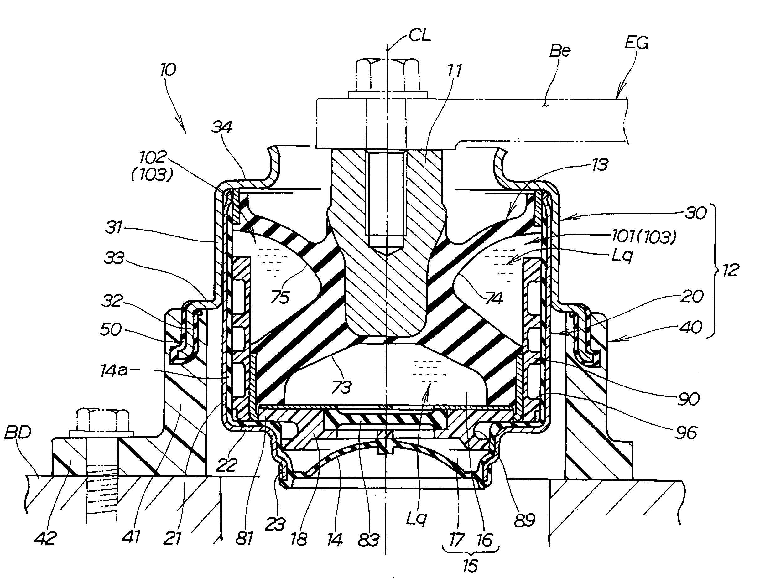
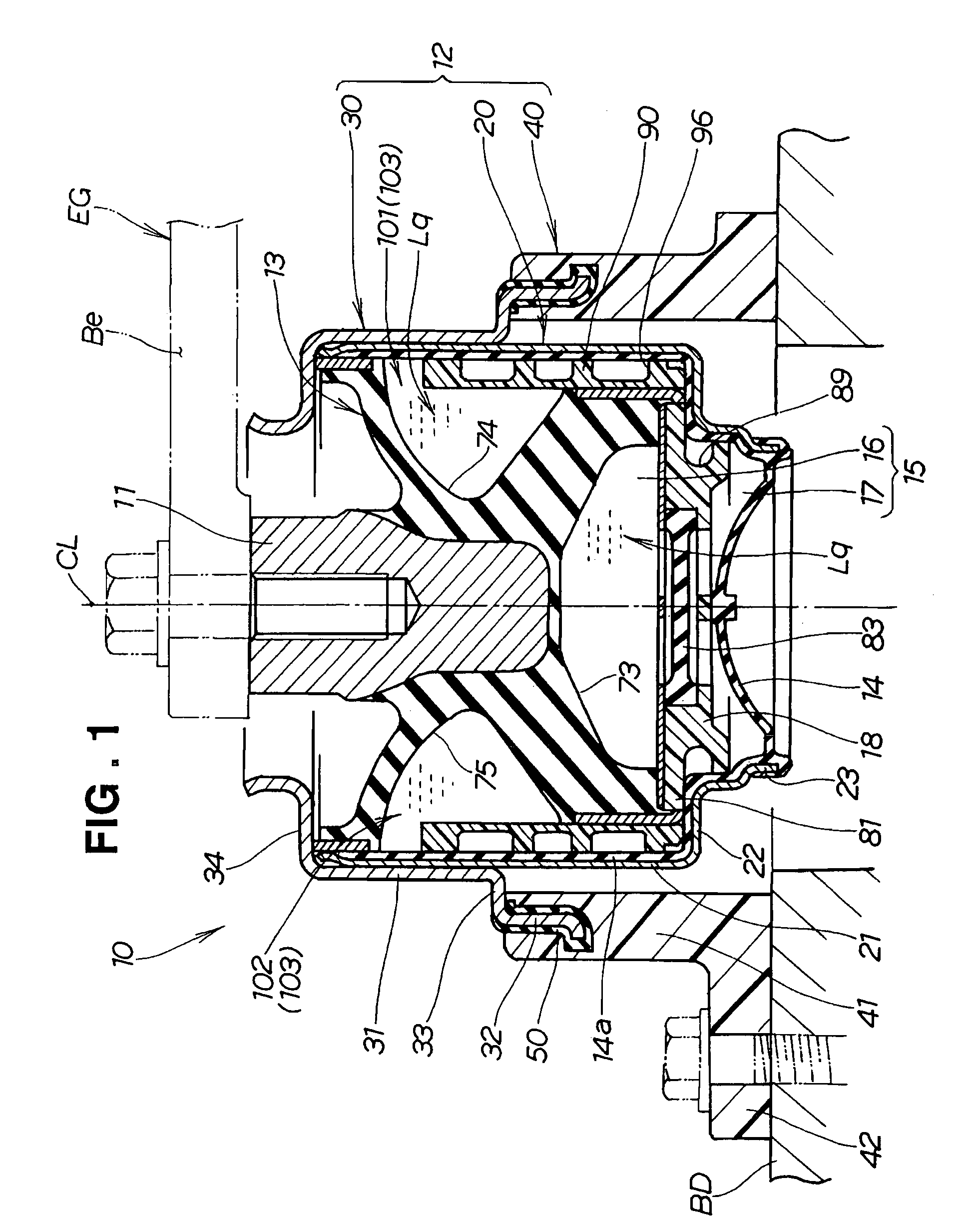
[0033]Referring now to the drawings and FIG. 1 in particular, there is shown in cross section a vibration isolation device 10 according to a first embodiment of the present invention. The vibration isolation device 10 in the illustrated embodiment is disposed between a body BD (as a support body) of a motor vehicle and an engine EG (as a vibratory source) of the motor vehicle for supporting the engine EG on the vehicle body BD in such a manner that vibration generated from the engine EG while running can be efficiently absorbed by the vibration isolation device 10 to thereby suppress transmission of the vibration from the engine EG to the support body BD. The illustrated vibration isolation device 10 is of the liquid-filled type.

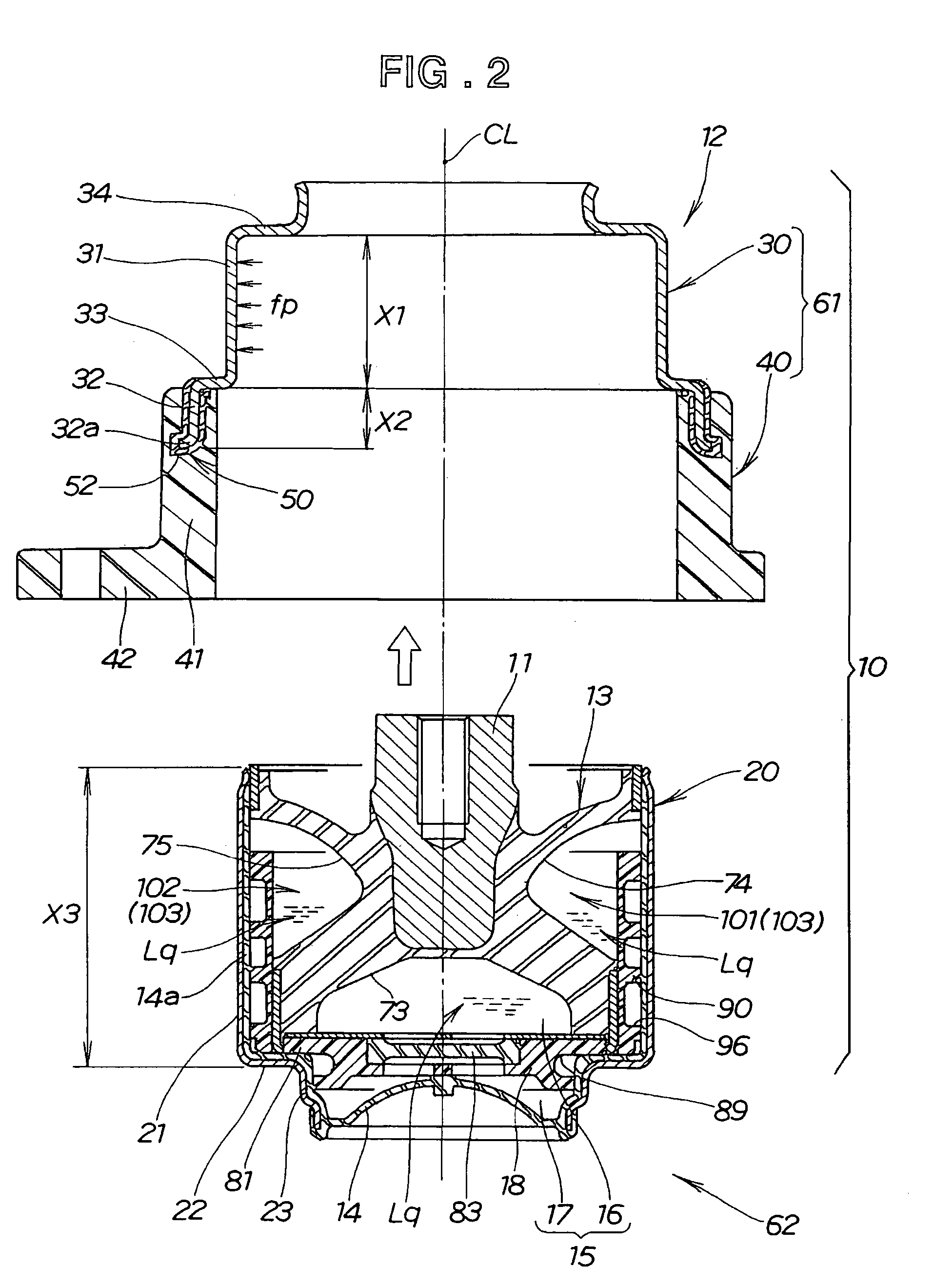
[0034]As shown in FIGS. 1 and 2, the liquid-filled vibration isolation device 10 generally comprises a first attachment member 11 for attachment to the engine EG, a second attachment member 12 of tubular shape for attachment to the vehicle body BD, an elasti...


PUM


Abstract

A vibration isolation device includes two attachment members inter-connected by an elastic member. One of the attachment members comprises a metal tubular member connected to the elastic member, a metal bracket in which the metal tubular member is press-fitted, and a plastic bracket supporting the metal bracket and adapted to be attached to a support body or a vibratory source. The metal bracket has an engagement portion press-fitted with the metal tubular member, and a non-engagement portion offset from the engagement portion in a radial outward direction and held out of press-fitted engagement with the metal tubular member, the non-engagement portion being connected to the plastic bracket with a second elastic member disposed therebetween.

Description

FIELD OF THE INVENTION[0001]The present invention relates to a vibration isolation device used for mounting a vibratory source to a support body.BACKGROUND OF THE INVENTION[0002]There are known various types of vibration isolation devices, which are so designed as to absorb vibration generated from a vibratory source such as an engine, thereby suppressing transmission of the vibration to a support body on which the vibrator source is mounted. One example of such known vibration isolation devices takes the form of a liquid-filled vibration isolation device, which comprises a first attachment member adapted to be attached to an engine as a vibratory source, a second attachment member of tubular shape adapted to be attached to a support body, an elastic member such as rubber interconnecting the first and second attachment members, and a diaphragm mounted to the second attachment member so as to define, together with the elastic member, a liquid chamber. A partition member is mounted to...

Claims


Application Information

Patent Timeline
Patent Type & Authority Patents(United States)
IPC IPC(8): F16M13/00
CPCF16F13/16F16F13/085
Inventor MIYAHARA, TETSUYAYANO, KATSUHISATANAKA, EIJI
Owner HONDA MOTOR CO LTD
Why Eureka
Try Eureka