Offshore wind turbine with multiple wind rotors and floating system

a wind turbine and floating system technology, applied in the direction of machines/engines, electric generator control, vessel construction, etc., can solve the problems of prohibitively large cost of this transmission system and may present navigation hazards in the foundation, so as to reduce the structural requirements of the tower and the ballast requirements of the hull. , the effect of reducing the weigh

Active Publication Date: 2006-07-11
OCEAN WIND ENERGY SYST
View PDF29 Cites 267 Cited by
  • Summary
  • Abstract
  • Description
  • Claims
  • Application Information

AI Technical Summary

Benefits of technology

[0015]Embodiments of the present invention also include methods for summing the power output from multiple wind turbine rotors, either electrically or mechanically. By summing the power from individual rotors as disclosed herein it is possible to decrease the weight located at the turbine hub and relocate the weight to the bottom of the tower thus reducing the structural requirements of the tower and the ballast requirements of the hull. The embodiments of power summation techniques described herein are useful for arrays of wind turbines located on land as well as offshore.

Problems solved by technology

The use of wind turbines to generate electricity offshore presents some unique challenges that are not encountered onshore.
Conventional offshore wind turbine foundations and pilings are a significant impact to the sea floor ecology and at the end of the turbine's life the foundation may present a navigation hazard.
The cost of this transmission system can be prohibitively large especially if the wind farm is very far from shore.
The placement of these prior art turbines offshore, but near land, has caused controversy because the turbines are easily visible from populated areas.
Often this equipment is heavy and located in a nacelle at the top of a tower which raises the center of gravity of the whole tower, turbine, and foundation system increasing the demands on the tower and foundation.

Method used


Image

  • Offshore wind turbine with multiple wind rotors and floating system
  • Offshore wind turbine with multiple wind rotors and floating system
  • Offshore wind turbine with multiple wind rotors and floating system

Examples


Embodiment Construction

[0042]In the following disclosure several embodiments of the invention are described to give illustrate (but not limit) the extent and usefulness of the invention. The term ‘wind turbine’ is used herein to describe the prime mover portion of a wind power production system and describes the aloft, non-tower, portions of the wind power production system. The term ‘wind turbine’ encompasses the drive train, gearbox, and generator for embodiments that include these elements. The word ‘rotor’ refers to the external rotating parts of a wind turbine, namely blades and a hub. As noted previously the word ‘windship’ is used herein to describe an offshore semi-submersible marine wind power system and the support structure for said system.

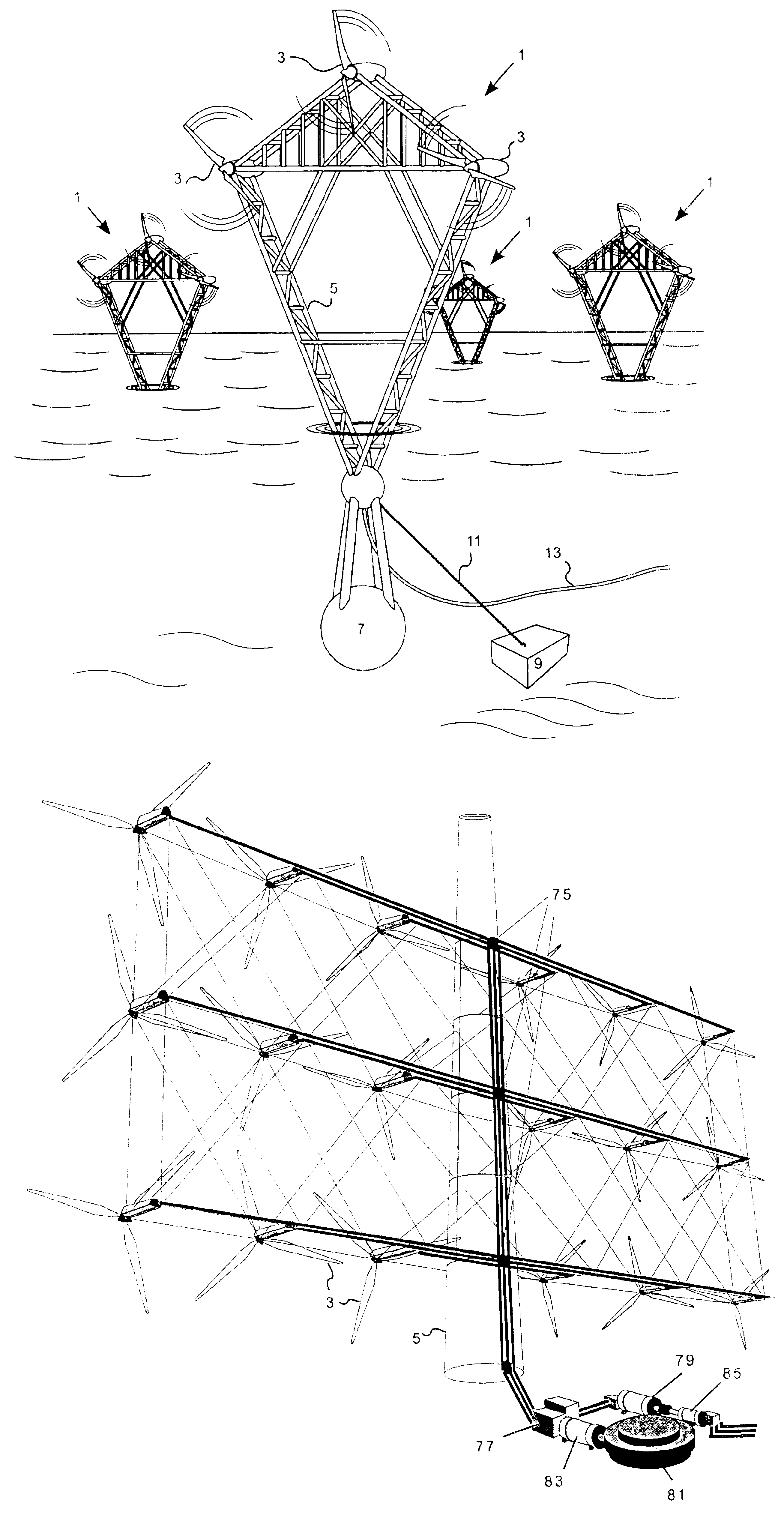
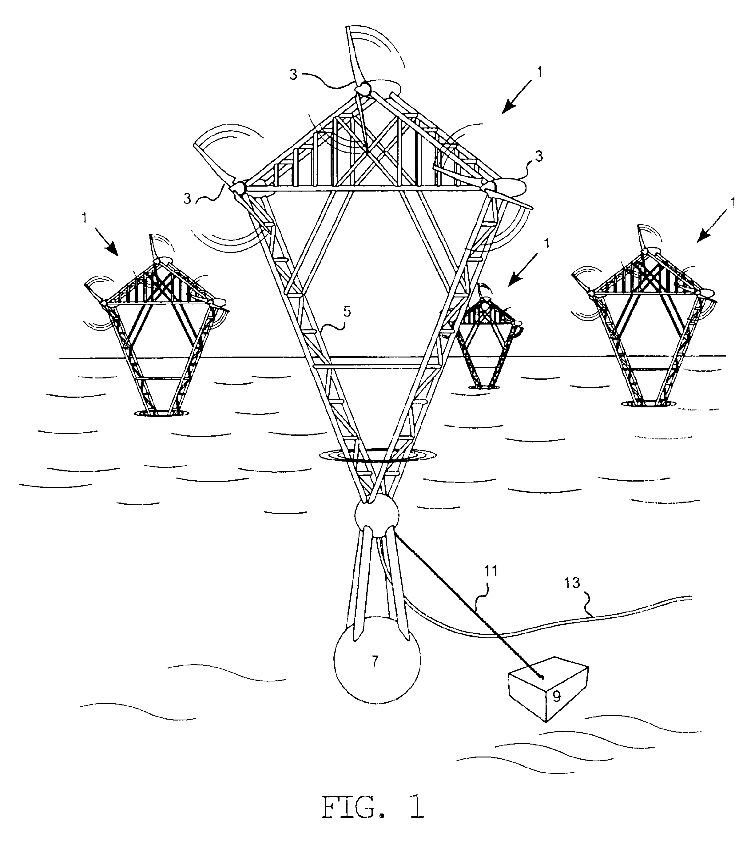
[0043]FIG. 1 shows four arrays of wind turbines 3, three to a tower 5, mounted at sea on windships 1 which are tethered to the seabed via anchors 9. In the foreground of FIG. 1 is an offshore wind turbine in the form of a windship 1 using three large rotors 3...


PUM


Abstract

A wind energy conversion system optimized for offshore application. Each wind turbine includes a semi-submersible hull with ballast weight that is moveable to increase the system's stability. Each wind turbine has an array of rotors distributed on a tower to distribute weight and loads and to improve power production performance where windshear is high. As much of the equipment associated with each rotor as possible is located at the base of the tower to lower the metacentric height. The equipment that may be emplaced at the bottom of the tower could include a power electronic converter, a DC to AC converter, or the entire generator with a mechanical linkage transmitting power from each rotor to the base of the tower. Rather than transmitting electrical power back to shore, it is contemplated to create energy intensive hydrogen-based products at the base of the wind turbine. Alternatively, there could be a central factory ship that utilizes the power produced by a plurality of wind turbines to create a hydrogen-based fuel. The hydrogen based fuel is transported to land and sold into existing markets as a value-added “green” product.

Description

RELATED APPLICATIONS[0001]This application claims priority under 35 U.S.C. § 119(e) to U.S. Provisional Patent Application No. 60 / 362,790 which was filed on Mar. 8, 2002 and which is incorporated herein by reference.FIELD OF THE INVENTION[0002]Embodiments of the invention relate to improvements in the field of wind power conversion systems. They further relate to summation of power output from multiple wind turbine rotors or other power sources. They further relate to the use of renewable energy, such as wind, used to create hydrogen gas. They further relate to using this hydrogen gas to create hydrogen-derivative fuels. Also, they encompass the mechanical marine systems used to support and maintain the wind turbines at sea and to transport the hydrogen and hydrogen-derivative fuels to land.BACKGROUND OF THE INVENTION[0003]Wind turbines have begun to be sited at offshore locations. The use of wind turbines to generate electricity offshore presents some unique challenges that are not...

Claims


Application Information

Patent Timeline
Patent Type & Authority Patents(United States)
IPC IPC(8): F03D9/00F03B13/00H02P9/04B63B35/44F03D1/02F03D11/04
CPCF03D9/00F03D11/04B63B35/44F05B2220/62F05B2240/93F05B2240/95Y02E10/723Y02E10/727Y02E70/10F05B2220/61B63B2001/044B63B2035/446E02B2017/0091B63B1/047F03D9/255F03D13/25Y02A20/141Y02E10/72Y02E60/36Y02P80/20
Inventor HERONEMUS, PHYLLIS R.HERONEMUS, WILLIAM
Owner OCEAN WIND ENERGY SYST
Why Eureka
Try Eureka