Method of reforming insulating film deposited on substrate with recess pattern

a technology of insulating film and recess pattern, which is applied in the direction of basic electric elements, semiconductor/solid-state device manufacturing, electric devices, etc., can solve the problems of poor quality of the film deposited on the sidewall portion of the trench, etc., to improve the properties improve the quality of the sidewall portion, and low atomic weight

Active Publication Date: 2019-05-07
ASM IP HLDG BV
View PDF2766 Cites 279 Cited by
  • Summary
  • Abstract
  • Description
  • Claims
  • Application Information

AI Technical Summary

Benefits of technology

[0007]Normally, deposition cycles of a film use a pressure of 100 Pa to 1,000 Pa, and when post-deposition reforming treatment is conducted to reform the film, the same pressure as in the deposition cycles is used according to conventional reforming processes. In contrast, in some embodiments of the present invention, by using an extremely low pressure such as about 1 Pa (with high RF power such as about 4 W / cm2) in post-deposition cycle reforming treatment, a sidewall portion of a film can significantly be reformed so as to improve properties of the sidewall portion of the film even when the aspect ratio of the trench is as high as 10. In some embodiments, all gas(es) used in the reforming treatment is / are an inert gas (e.g., inactive in a non-excited state) having a low atomic weight. In some embodiments, the reforming gas is constituted by or consists of H2. The film such as that deposited by PEALD contains hydrogen as an impurity, and in non-limiting theory, by exposing the film to hydrogen ions and radicals under certain conditions (e.g., at an extremely low pressure), contaminant hydrogen can be dissociated and removed from the film, effectively from the sidewall portion, thereby converting the film to a film with a high purity. In some embodiments, He is used in combination with or in place of H2. In some embodiments, when the pressure of the reforming treatment is 10 Pa or less, improvement on the properties of the sidewall portion (such as resistance to wet etching) becomes pronounced, and when the pressure is 2 Pa or less, the properties of the sidewall portion of the film can become equivalent to those of the top portion of the film. In non-limiting theory, by using an extremely low pressure during the reforming treatment, the mean free path of ions / radicals of small molecules can be prolonged and ions / radicals can travel through the gas phase and reach the sidewalls of a trench at an increased probability, and also, radicals having an extended life may be generated by ions, thereby reaching the sidewalls of a trench at an increased probability.

Problems solved by technology

However, even though a film deposited by PEALD has a high conformality, the quality of the film is not uniform throughout the film and varies depending on the geometrical location of a portion of the film.
That is, a portion of the film deposited on a top surface typically has high quality, whereas a portion of the film deposited on sidewalls of a trench typically has poor quality.
The poor quality of the sidewall portion of the film becomes a problem when forming a vertical spacer in the process of SDDP, for example, wherein the film deposited by PEALD on a recess pattern of a substrate is subjected to etching to remove portions of the film deposited on a top surface and on a bottom surface of the recess pattern, leaving a portion of the film deposited on sidewalls of the recess pattern, so as to form vertical spacers which are used as a mask to transfer a pattern to a template.
PEALD uses a plasma containing ions which have directionality (anisotropy), and thus, insufficient ion bombardment occurs on sidewalls of a trench, and as a result, the quality of a portion of the film deposited on the sidewalls is inferior to that of a portion of the film deposited on a top surface or bottom surface of the trench.
However, as miniaturization of a recess pattern becomes more prevalent, it becomes more difficult to obtain a film having satisfactory profiles, particularly, satisfactory quality of sidewall portion of the film.

Method used


Image

  • Method of reforming insulating film deposited on substrate with recess pattern
  • Method of reforming insulating film deposited on substrate with recess pattern
  • Method of reforming insulating film deposited on substrate with recess pattern

Examples


example 1

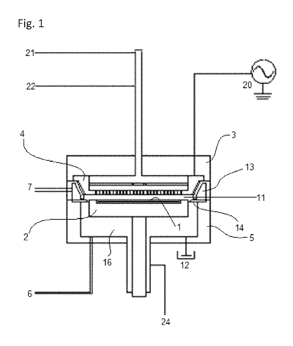
[0065]A substrate (having a diameter of 100 mm and a thickness of 0.7 mm) having a SiO2 film deposited by PEALD was provided wherein the substrate had trenches with an opening width of approximately 30 nm and a depth of approximately 300 nm (an aspect ratio of 10). The SiO2 film was formed on an underlying layer (SiN) by PECVD with a thickness of about 15 nm on the substrate, which underlying layer was formed in order to adjust the shapes of the trenches before depositing the SiO2 film wherein the trenches of the substrate with the underlying film had an opening width of approximately 60 nm and a depth of approximately 300 nm (an aspect ratio of 5). Reforming treatment was conducted on the substrate using a sequence illustrated in FIG. 13 under the conditions shown in Table 2 below using the apparatus illustrated in FIG. 12, wherein the film was deposited using the apparatus illustrated in FIG. 1 which was hermetically connected to the apparatus for reforming process via a wafer han...

example 2

[0071]Substrates with insulating films (with an aspect ratio of 10) were provided as described in Example 1 and were reformed under the conditions used in Example 1 (a pressure of 1 Pa) except that the reforming gas was changed as shown in Table 4 below, to determine resistance to wet etching at the sidewalls of trenches.

[0072]

TABLE 4(numbers are approximate)Reforming gasΔSide - Etched thickness (nm)Example 2H22Comp. Ex. 3N25Comp. Ex. 4O28Comp. Ex. 5Ar8

[0073]As shown in Table 4, when using H2 gas, the resistance to wet etching was significantly improved in Example 2, as compared with the use of N2 (Comparative Example 3), O2 (Comparative Example 4), and Ar (Comparative Example 5).

[0074]Further, in Example 2, the concentration of hydrogen atoms in the film before the reforming treatment was 7×10²¹ atms / cm3, and the concentration of hydrogen atoms in the film after the reforming treatment was reduced to 2×10²¹ atms / cm3 (which was determined using X-ray fluorescence analysis).

example 3

[0075]A substrate (having a diameter of 100 mm and a thickness of 0.7 mm) having a SiO2 film deposited by PEALD was provided wherein the substrate had trenches with a width of approximately 30 nm and a depth of approximately 300 nm (with an aspect ratio of 10). The SiO2 film was formed by PEALD with a thickness of about 7 nm on the substrate and a conformality of about 100%. Reforming treatment was conducted on the substrate using a sequence illustrated in FIG. 13 under the conditions shown in Table 5 below using the apparatus illustrated in FIG. 12. Multiple films were treated under partially different conditions of reforming treatment for analysis (see FIG. 8). The reformed film was subjected to wet etching (dipped in a solution of DHF 1000:1 for 10 minutes) and analyzed for resistance to wet etching. The results are shown in FIG. 8.

[0076]

TABLE 5(numbers are approximate)Conditions for Reforming ProcessSubstrate temperatureNo heating (room temperature)Electrode gap80 mmPressure dur...


PUM


Abstract

A method of reforming an insulating film deposited on a substrate having a recess pattern constituted by a bottom and sidewalls, includes: providing the film deposited on the substrate having the recess pattern in an evacuatable reaction chamber, wherein a property of a portion of the film deposited on the sidewalls is inferior to that of a portion of the film deposited on a top surface of the substrate; adjusting a pressure of an atmosphere of the reaction chamber to 10 Pa or less, which atmosphere is constituted by H2 and / or He without a precursor and without a reactant; and applying RF power to the atmosphere of the pressure-adjusted reaction chamber to generate a plasma to which the film is exposed, thereby reforming the portion of the film deposited on the sidewalls to improve the property of the sidewall portion of the film.

Description

BACKGROUND OF THE INVENTION[0001]Field of the Invention[0002]The present invention generally relates to a method of reforming an insulating film deposited on a substrate having a recess pattern, particularly reforming a portion of the film deposited on sidewalls of the recess pattern.[0003]Description of the Related Art[0004]A SiO2 film deposited by plasma-enhanced atomic layer deposition (PEALD) is widely used in the Semiconductor manufacturing industry, since the conformality of such a film is very high, e.g., 100%, when being deposited in a trench having an aspect ratio of about 10. This film profile is important to fabrication processes such as a process of pattern transfer and target etching using spacer-defined double patterning (SDDP), wherein forming vertical spacers with accurate dimensions is important to improve resolution. However, even though a film deposited by PEALD has a high conformality, the quality of the film is not uniform throughout the film and varies dependin...

Claims


Application Information

Patent Timeline
Patent Type & Authority Patents(United States)
IPC IPC(8): H01L21/3105H01L21/02H01L21/033
CPCH01L21/0234H01L21/0228H01L21/02318H01L21/02274H01L21/0337H01L21/0332H01L21/02164H01L21/0217H01L21/02178H01L21/02211H01L21/02219H01L21/3105H01L21/31111H01L21/31116
Inventor KOBAYASHI, AKIKOZAITSU, MASARUKOBAYASHI, NOBUYOSHIHORI, MASARU
Owner ASM IP HLDG BV
Why Eureka
Try Eureka