Methods and devices for continuous suture passing

a technology of continuous suture and needle, which is applied in the field of surgical stitching devices, can solve the problems of protruding needles being caught in tissue, limited maneuverability of most currently available suturing instruments,

Inactive Publication Date: 2011-04-14
CETERIX ORTHOPAEDICS
View PDF99 Cites 48 Cited by
  • Summary
  • Abstract
  • Description
  • Claims
  • Application Information

AI Technical Summary

Benefits of technology

The first jaw may include a first tissue contacting surface and the second jaw comprises a second tissue contacting surface, and further wherein the first tissue contacting surface and the second tissue contacting surface are substantially parallel when the jaws are open. Parallel opening of the jaws may allow larger thickness or areas of tissue to be grasped or manipulated (e.g. sutured), because as the jaws close they apply approximately the same force over a large area of the tissue, rather than over a small region. This may prevent “pinching” or damage to tissue, particularly near the region in which the jaws are hinged. Furthermore, the suture passer jaws may also act as a tissue clamp or grasper, holding the tissue securely as the suture is passed through it.
A jaw control may be a proportional control that is limited. Thus, a limiter may be included to limit the motion of the jaw(s) when the jaw control is used. A limiter may prevent the jaws from applying pressure above some threshold, preventing or limiting damage to the tissue, while still allowing it to be secured between the jaws. In some variations, this limiter is adjustable. The limiter may not completely prevent additional pressure from being applied, but it may limit it by, for example, increasing the proportionality of the proportional jaw control. Thus, as more force is applied to the control, smaller and smaller percentages of this force are translated to the tissue (either linearly or above a threshold). The force applied may be fed back to the limiter along the control mechanism. For example, the limiter may be in communication with the mechanical control mechanism (e.g., cables, pushers, etc.), pneumatic control mechanism, magnetic control mechanism, electric control mechanism, etc. In some variations, the limiter limits force applied by the jaws when the force exceeds about 20 lb (or about 5 lb, about 10 lb, about 15 lb, about 25 lbs, etc.). The linkage between the jaw movement and the jaw control may include a mechanical advantage (e.g., approximately 1.25:1). Thus, if you apply 1 pound of force to the jaw control, the jaw exerts 1.25 pounds of clamping force on the tissue over a range of pressures (particularly in variations including a limiter).
In addition to the jaw control, the handle of a suture passer may include additional controls that can control other aspects of the device, such as the angle of deflection of the distal end of the device. Thus, in some variations the distal end of the device (e.g., including the jaws or a portion of the jaws) may be bent or deflected. Deflection of the distal end may help improving steering of the device within a subject's body, as well as improving access to difficult to reach regions. In some variations, the handle includes a distal tip deflector control that is configured to control deflection of the distal end of the device.
Also described herein are continuous suture passers having suture channels, passages or guides for controlling the position of the suture with respect to the distal and / or intermediate region of the suture passer as the suture passer is operated. For example, a suture passer may include a first jaw and a second jaw, a handle including a jaw control to manipulate at least one jaw, and a first suture shuttle dock functionally connected to the first jaw, wherein the first suture shuttle dock is configured to releasably secure a suture shuttle so that the suture shuttle may be passed between the first and second jaws. The first suture shuttle dock may include a suture passage to at least partially guide a suture connected to the suture shuttle when the suture shuttle is engaged with the first suture shuttle dock. The suture passage (or guide) may allow the shuttle to reside completely within the jaws, and because it prevents the suture from interfering with the penetrator as the tissue penetrator passes through tissue or interacts with the opposite jaw (e.g., a shuttle dock region on the opposite jaw).
In some variations, the suture passer also includes an intermediate region between the first and second jaws and the handle that has a suture channel that is configured to guide the suture extending from the first or second jaws. For example, the suture channel may be an opening extending longitudinally along the intermediate region. Thus, the suture channel may prevent the suture from impinging between the shaft of the device an inner wall of a cannula which may be used to position the suture passer, particularly in endoscopic and arthroscopic applications.
Also described herein are suture shuttles. A suture shuttle may include a suture attachment region configured to secure to a surgical suture, a shuttle body having an outer surface that is substantially blunt, and a shuttle retainer region configured to engage a tissue penetrator to retain the suture shuttle in communication with the tissue penetrator. The shuttle body region may have an outer diameter that is less than 5 mm. The suture shuttles described herein may also include a shuttle alignment feature, wherein the shuttle alignment feature communicates with a region of the tissue penetrator and a region of a suture shuttle dock to orient the suture shuttle. A shuttle alignment feature may help organize and control the suture attached to the suture shuttle. For example, by helping position the suture into a suture guide or channel as the suture shuttle is passed between the jaws of a suture passer. A shuttle alignment feature may include a groove in the shuttle body.

Problems solved by technology

Arthroscopic rotator cuff repair is one example of a technically challenging procedure that requires the placement of sutures in difficult to reach regions, as well requiring precise placement of sutures.
Furthermore, most currently available suturing instruments are limited in their ability to be maneuvered, particularly over thicker tissue regions.
At least one end of the needle protrudes from one or the other jaw at all times. The protruding needle may become caught in tissue, a problem that is exacerbated in difficult to access regions and regions offering limited maneuverability, such as the subacromial space of the jaw.

Method used


Image

  • Methods and devices for continuous suture passing
  • Methods and devices for continuous suture passing
  • Methods and devices for continuous suture passing

Examples


Embodiment Construction

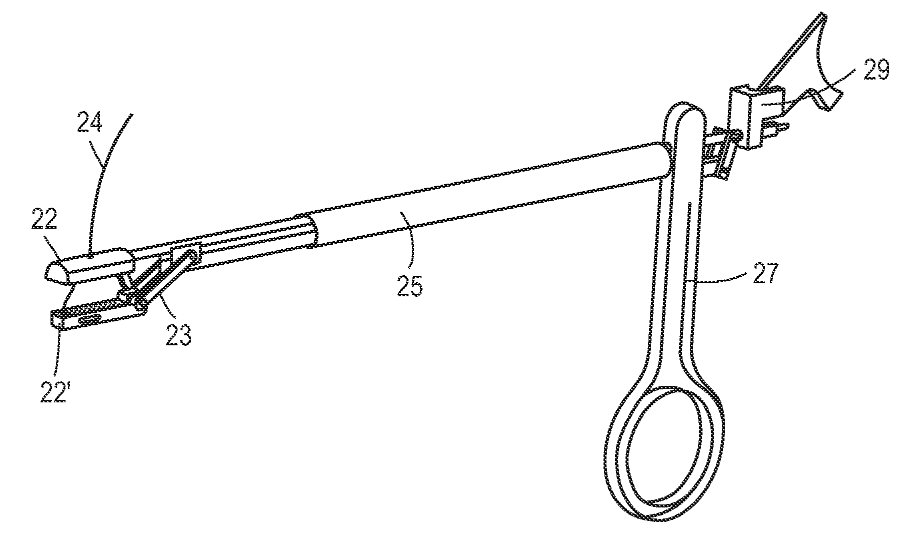
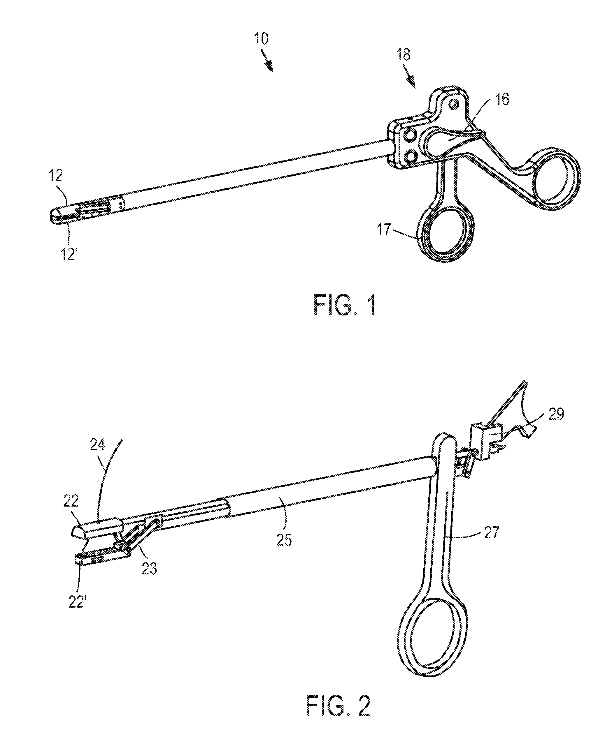
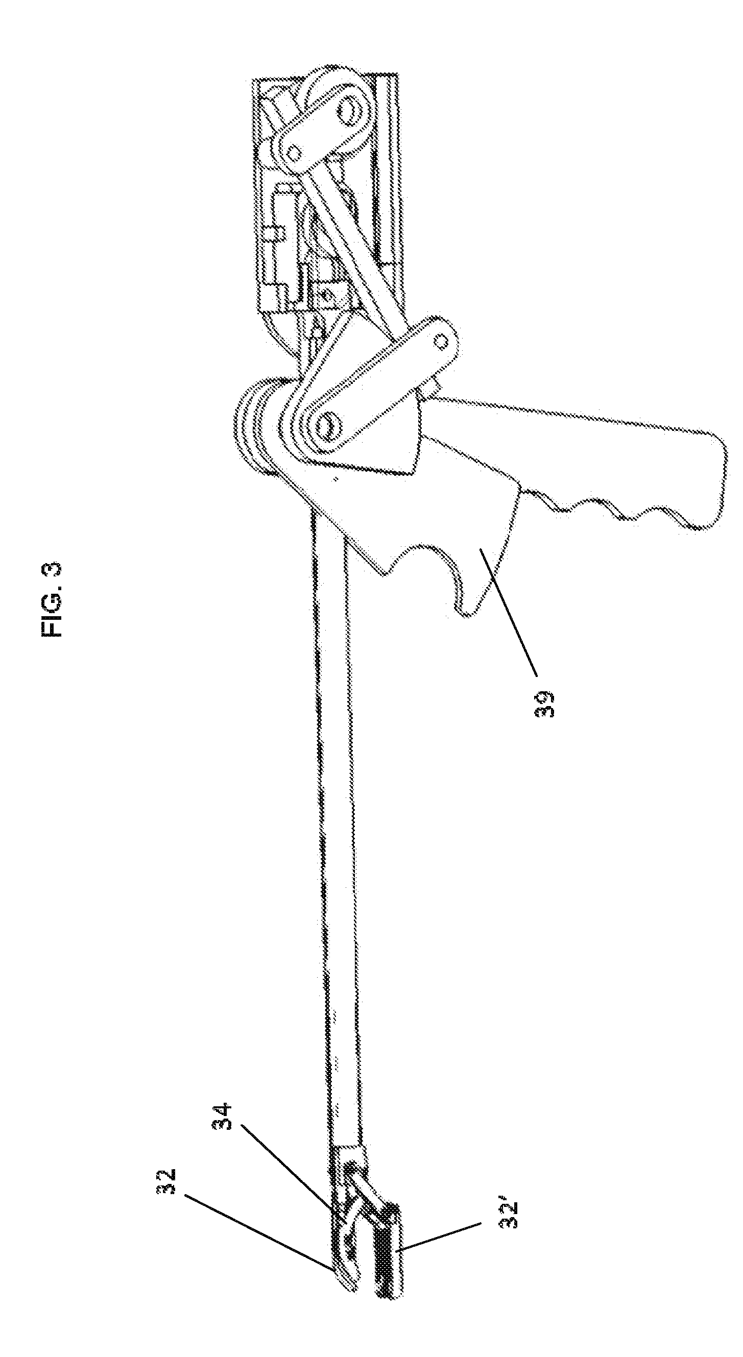
Described herein are suture passers for passing a suture through tissue, as well as systems including suture passers, and methods of passing sutures through tissue. In general, the suture passers described herein are continuous suture passers that are configured to pass a suture back and forth through a tissue without having to reload the device. Thus, these devices may be used for continuous stitching of tissue.

FIG. 1 illustrates one variation of a continuous suture passer 10, including some of features that may be included in a continuous suture passer. In general, the suture passers described herein may include a distal, tissue-contacting region and a proximal region having a handle or other user interface. The distal end of the device may be separated from the proximal end of the device by an elongate intermediate region. The intermediate region may be any appropriate length, and may be straight (as shown in FIG. 1) or it may be curved or otherwise shaped. In some variations, th...


PUM


Abstract

Suture passers for suturing tissue in a continuous manner by passing a suture attached to a suture shuttle through. A suture passer may include a first jaw, a second jaw, and a tissue penetrator that is retractable and extendable from the first jaw. The tissue penetrator may have a suture shuttle engagement region, and the second jaw may include a shuttle dock. The suture shuttle may be transferred between the first and second jaws as the tissue penetrator is extended from the first jaw and engages the second jaw. In some variations of the tissue passer, one or both jaws are tissue penetrating. In some variations, the jaws open in parallel, allowing large tissue regions to be positioned between the jaws. Methods of using these devices are also described, as are systems and kits including these devices.

Description

BACKGROUND OF THE INVENTIONThis invention relates to surgical stitching devices by which a stitch or continuous stitches may be made during surgery.Suturing instruments for assisting a medical practitioner in placing stitches during surgical procedures are useful, particularly in surgical (procedures requiring the placement of secure and accurate sutures in difficult to access regions of the body, including internal body regions. Instruments and methods for suturing remotely are especially important in minimally invasive surgical procedures such as laproscopic and endoscopic procedures. In addition to helping to access remote regions of the body requiring suturing, suturing instruments may also allow the efficient manipulation of very small needles and the formation of small and precise suturesArthroscopic rotator cuff repair is one example of a technically challenging procedure that requires the placement of sutures in difficult to reach regions, as well requiring precise placement...

Claims


Application Information

Patent Timeline
Patent Type & Authority Applications(United States)
IPC IPC(8): A61B17/04
CPCA61B17/0491A61B2017/0609A61B2017/06052A61B2017/06047
Inventor SALIMAN, JUSTIN D.SHAHOIAN, ERIK
Owner CETERIX ORTHOPAEDICS
Why Eureka
Try Eureka