
Turntable and display apparatus

a technology of display apparatus and turntable, which is applied in the direction of couplings, rod connections, furniture parts, etc., to achieve the effect of stable rotation operation, reduced variation in rotational resistance, and stable friction for

Inactive Publication Date: 2010-05-04
MITSUBISHI ELECTRIC CORP
View PDF18 Cites 24 Cited by
  • Summary
  • Abstract
  • Description
  • Claims
  • Application Information

AI Technical Summary

Benefits of technology

[0011]The present invention is intended to solve the above described problems, and an object of the present invention is to provide a turntable enabling a stable manual rotation (operation) of the display portion, and enabling miniaturization.
[0013]With such an arrangement, friction forces can be obtained at the sliding contact portion between the fixed member and the first friction plate, the sliding contact portion between the first friction plate and the second friction plate, and the sliding contact portion between the second friction plate and the rotatable member. Therefore, it becomes possible to generate a stable friction force which is less influenced by the change of shapes of the respective members. As a result, it becomes possible to reduce the variation in the rotational resistance when the user manually rotates the display portion, and the rotating operation becomes stable.
[0014]Furthermore, with the configuration in which the weight of the display portion is applied to the respective sliding contact portions, it becomes unnecessary to provide a separate urging mechanism. As a result, the configuration of the turntable becomes simple, and the weight of the turntable decreases. Further, by adjusting the weight of the display portion, the friction force (i.e., the rotational resistance) can be adjusted in a simple manner.

Problems solved by technology

Furthermore, with the configuration in which the weight of the display portion is applied to the respective sliding contact portions, it becomes unnecessary to provide a separate urging mechanism.

Method used


Image

  • Turntable and display apparatus
  • Turntable and display apparatus
  • Turntable and display apparatus

Examples


embodiment 1

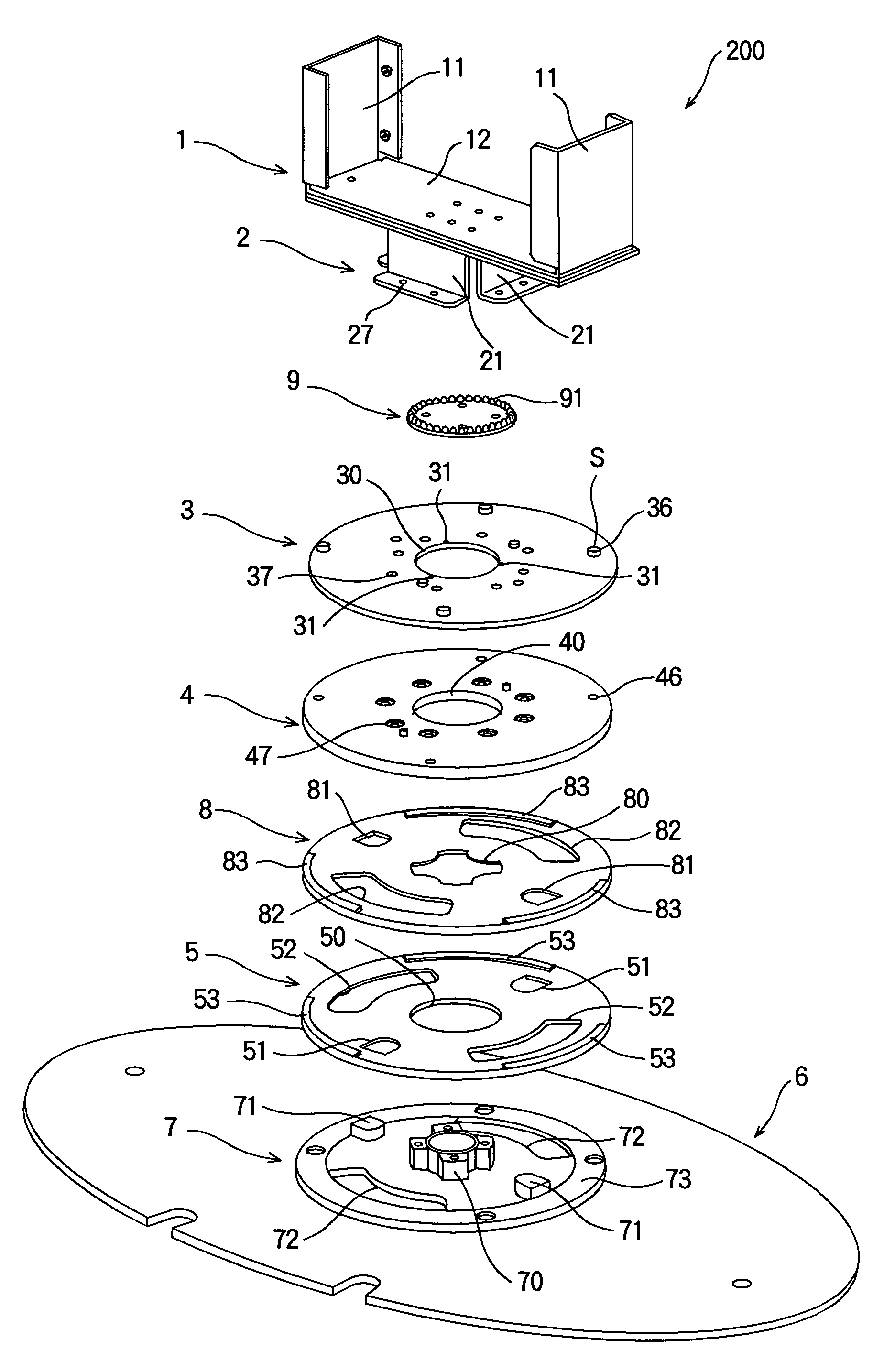
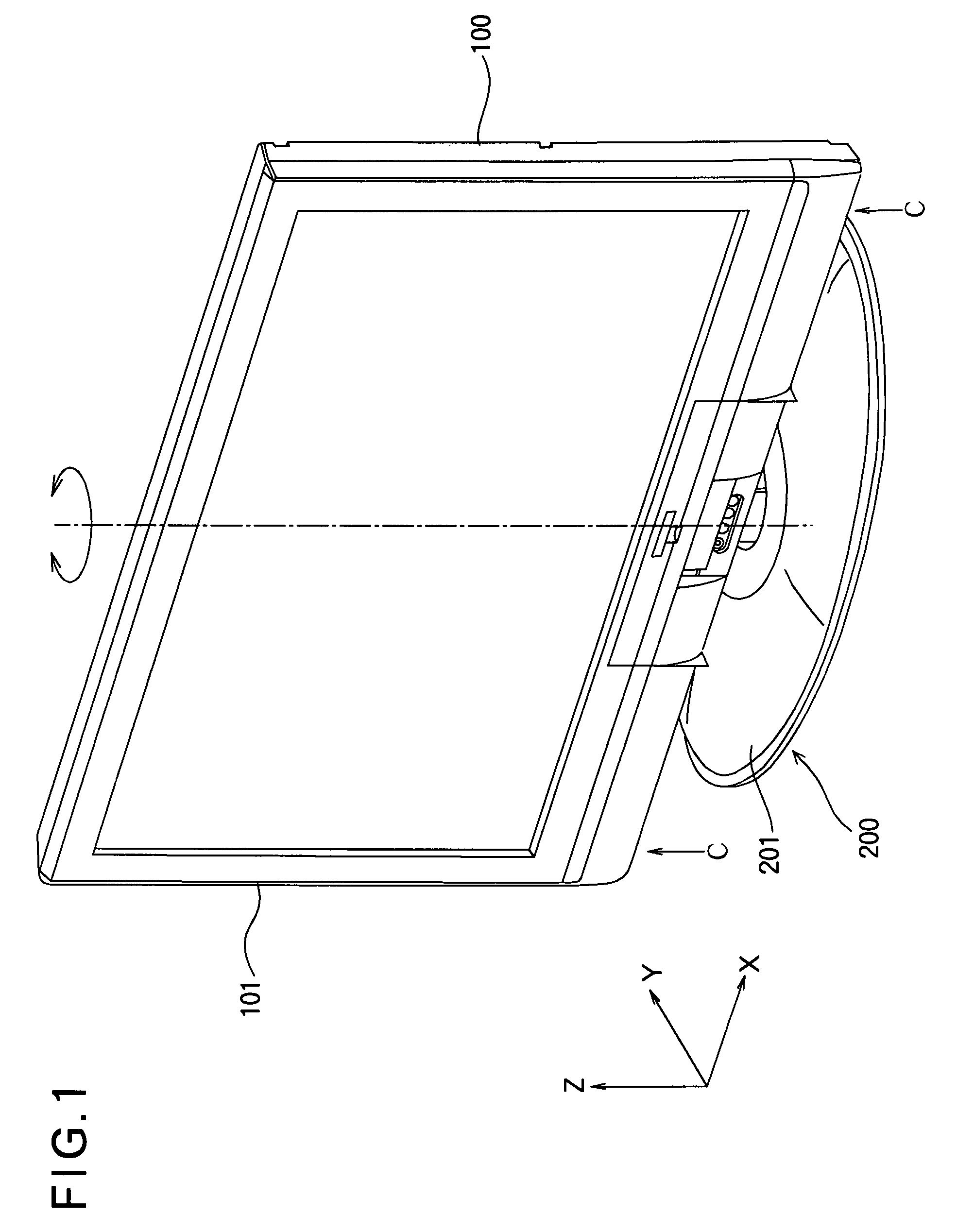
[0028]FIG. 1 is a perspective view showing the external shape of a display apparatus according to Embodiment 1 of the present invention. The display apparatus includes a display portion 100 having a display screen 101 for displaying an image or the like, and a turntable 200 on which the display portion 100 is mounted. The display portion 100 is, for example, an LCD television. The turntable 200 supports the display portion 100 so that the display portion 100 is rotatable about a vertical rotation axis (as an axis line) defined as Z-axis. By rotating the display portion 100, the display screen 101 can be oriented toward a user (viewer). The rotation axis is defined at, for example, a center position of the display screen 101 in the horizontal direction. A plane perpendicular to the Z-axis is defined as XY-plane.

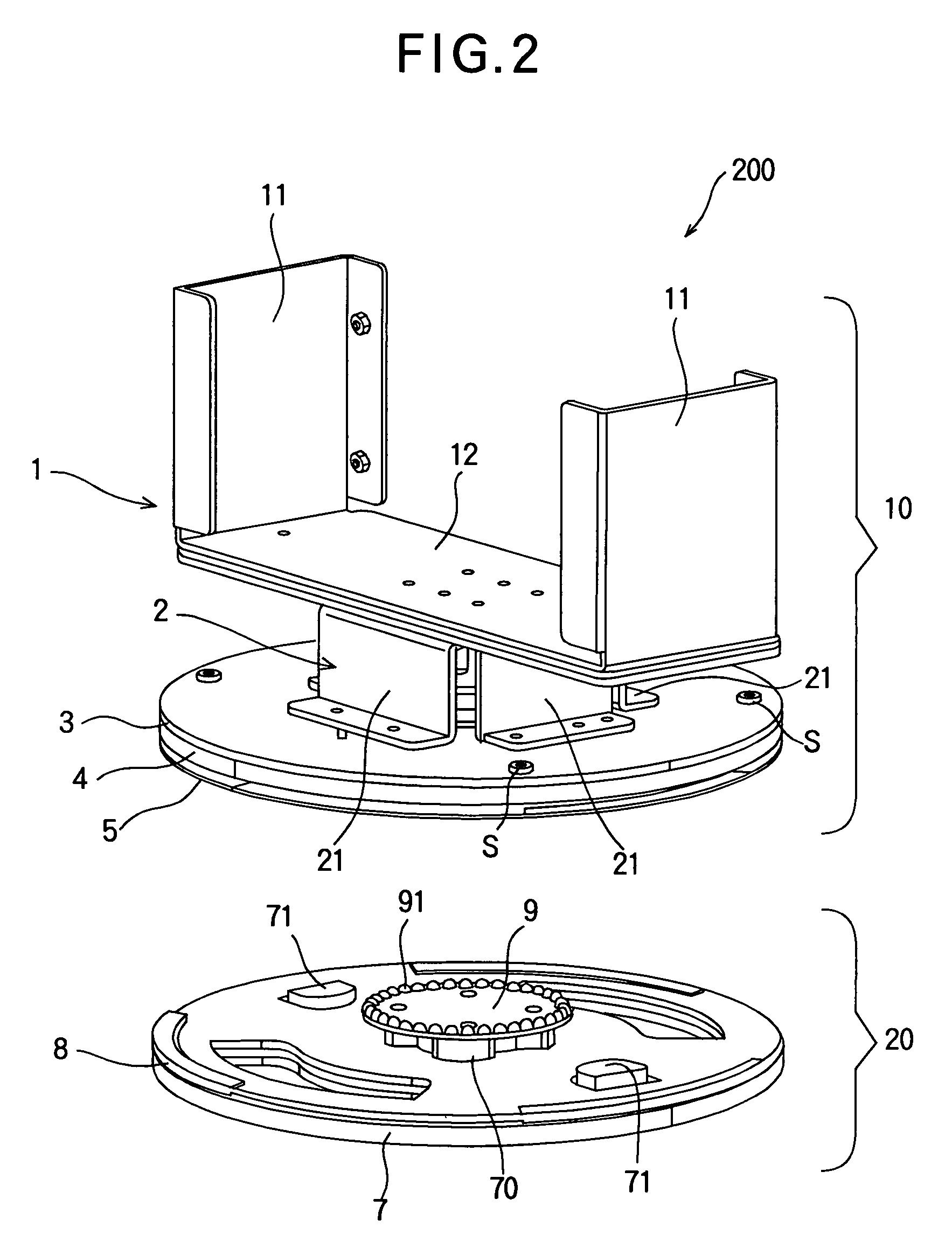
[0029]FIG. 2 is a perspective view showing the internal configuration of the turntable 200 in such a manner that the turntable 200 is divided into a rotatable unit and a fixed...

embodiment 2

[0057]In the above described Embodiment 1, the turntable 200 has one first friction plate 5 and one second friction plate 8. However, it is also possible to provide a plurality of the first friction plates and a plurality of the second friction plates. By changing the number of the first and second friction plates, the friction force (the rotational resistance) can be adjusted.

[0058]FIG. 9 is a schematic view showing a configuration example having another pair of a first friction plate 15 and a second friction plate 18, in addition to the first friction plate 5 and the second friction plate 8. In FIG. 9, components that are the same as those having been described in Embodiment 1 are assigned the same reference numerals.

[0059]In the configuration example shown in FIG. 9, the first friction plate 15, the second friction plate 18, the first friction plate 5, the second friction plate 8 are disposed between the fixed plate 7 and the rotatable plate 4 in this order from the fixed plate 7...

embodiment 3

[0062]In the above described Embodiment 1, the concaves 91 are formed on the retaining plate 9, and the protrusions 31 (engaging the concaves 91) are formed on the rotatable base 3. However, it is possible to provide the concaves on the rotatable base 3 and to provide the protrusions on the retaining plate 9.

[0063]FIG. 10 shows a configuration example where concaves 35 are provided on the rotatable base 3 and where protrusions 95 (engaging the concaves 35) are formed on the retaining plate 9. In FIG. 10, components that are the same as those having been described in Embodiment 1 are assigned the same reference numerals.

[0064]In the configuration example of FIG. 10, the concaves 35 of the rotatable base 3 and the protrusions 95 of the retaining plate 9 are able to engage each other at predetermined rotational positions. The other configuration is the same as Embodiment 1. In the configuration example of FIG. 10, even if the turntable 200 is going to rotate relative to the display por...


PUM


Abstract

A turntable includes a rotatable member rotatable together with a display portion about a predetermined axis line, a fixed member disposed on one side of the rotatable member in a direction of the axis line, a first friction plate whose rotation about the axis line is restricted by the rotatable member (and movable relative to the rotatable member in a direction of the axis line), and a second friction plate whose rotation about the axis line is restricted by the fixed member (and movable relative to the fixed member in a direction of the axis line). The first friction plate and the second friction plate are disposed between the fixed member and the rotatable member in a direction of the axis line. At least, a sliding contact portion between the fixed member and the first friction plate, a sliding contact portion between the first friction plate and the second friction plate, and a sliding contact portion between the second friction plate and the rotatable member are provided.

Description

BACKGROUND OF THE INVENTION[0001]This invention relates to a turntable of a display apparatus, and particularly relates to a turntable that can be manually rotated.[0002]A display apparatus such as an LCD (Liquid Crystal Display) television uses a turntable to adjust the orientation of a display portion. A conventional turntable includes a base on which the display portion is placed. The base is rotated by a motor via a power transmission mechanism. In order to prevent a finger or the like of a user from being caught between the display portion and its surrounding object, the power transmission from the motor to the base is disconnected under given conditions.[0003]To be more specific, a first rotation-transmission body linked to the motor and a second rotation-transmission body for rotating the base are coaxially mounted on the same rotation shaft. The rotation of the motor is transmitted to the base due to the friction force between the first and second rotation-transmission bodie...

Claims


Application Information

Patent Timeline
Patent Type & Authority Patents(United States)
IPC IPC(8): F16M13/00A47B91/00A47F5/00A47F7/00F16B7/10F16C11/00F16M11/00F16M11/06F16M11/08
CPCF16M11/08F16M11/22Y10T403/32557Y10T403/32549F16M2200/08
Inventor WATANABE, NORIHIROMICHIMORI, ATSUSHIHOMMA, TETSUJITANAKA, MASUMI
Owner MITSUBISHI ELECTRIC CORP
Learn More