Polyaxial bone anchor with headless pedicle screw

a technology of headless screws and polyaxial screws, applied in the field of bone fixation devices, can solve the problems of large size, difficulty in spinal fixation and stabilization methods, and often out of alignment of anchor heads, so as to facilitate pivoting and/or rotation, facilitate locking of anchor members, and lessen the likelihood of anchor members inadvertently separating

Inactive Publication Date: 2009-08-13
DEPUY SYNTHES PROD INC
View PDF10 Cites 179 Cited by
  • Summary
  • Abstract
  • Description
  • Claims
  • Application Information

AI Technical Summary

Benefits of technology

[0008]The locking element, internal sleeve, and anchor head have features that allow the locking element to rotate and / or pivot within the anchor head. This in turn allows the anchor member to angulate in all directions around and away from a central axis running through a bottom opening in the anchor head. The anchor member may then be locked at a desired angle and direction with respect to the anchor head.
[0009]The locking element, which may be a collet or collet-styled bushing, has a spherical or at least a partially spherical exterior shape. This spherical exterior shape allows the locking element to rotate and / or pivot within the anchor head, which in turn allows the anchor member to angulate in all directions about the central axis. The interior area of the locking element is sized and shaped slightly smaller than the size and shape of the non-threaded shank portion of the anchor member in order that the locking element be snap-fitted over the non-threaded shank portion. The locking element has a plurality of resilient fingers that radially expand to initially receive the non-threaded shank portion. Preferably, each finger has an interior ridge that sits in the external groove of the non-threaded shank portion when that portion is fully received in the locking element. This ridge-groove feature lessens the likelihood of the anchor member inadvertently separating from the locking element. The locking element preferably is configured to receive at least the uppermost portion of the non-threaded shank portion, with the remaining portion of the anchor member extending through the bottom opening of the anchor head.
[0010]The generally cylindrical internal sleeve has a bottom surface that preferably tapers or curves inward and upward such that when positioned in the anchor head it contacts the top exterior surface of the locking element fingers. This facilitates locking of the anchor member to the locking element, while allowing pivoting or rotation of the locking element prior to locking. In particular, when the anchor member is ready to be locked (i.e., the anchor member is positioned as desired), the fastener is tightened, causing the bottom surface of the internal sleeve to press down on the outside of the locking element fingers, which compress around the non-threaded shank portion to lock the position of the anchor member.
[0011]The anchor head has a lower portion with an interior surface around the bottom opening that is preferably tapered or spherically or partially spherically shaped to substantially match and contact a portion of the exterior surface of the locking element. This also facilitates pivoting and / or rotation of the locking element within the anchor head prior to locking.
[0012]By not requiring the typically large heads of known anchor members in order to provide polyaxial capability, a polyaxial bone anchor, and in particular its anchor head, can have a small size. This small size advantageously improves the versatility of the bone anchor.

Problems solved by technology

Surgeons may encounter difficulty with spinal fixation and stabilization methods because of difficulty aligning the spinal rod(s) with the U-shaped channels in the anchor heads.
For example, anchor heads are often out of alignment with one another because of the curvature of the spine or the size and shape of each vertebrae.
A disadvantage of many polyaxial bone anchors is their large size, particularly that of the anchor head, which tends to be large in order to accommodate the typically bulbous or ball-shaped end of the anchor member.
However, such large polyaxial bone anchors may have limited application in view of the confined space around the human spine.

Method used


Image

  • Polyaxial bone anchor with headless pedicle screw
  • Polyaxial bone anchor with headless pedicle screw
  • Polyaxial bone anchor with headless pedicle screw

Examples


Embodiment Construction

[0018]The invention can be used to treat various spinal disorders including, for example, degenerative and other instabilities due to decompression, tumors, infections, and fractures.

[0019]Note that while the polyaxial bone anchor is described and illustrated herein with reference to certain preferred or exemplary embodiments, the invention should not be limited to those preferred or exemplary embodiments. Furthermore, the features described and illustrated herein can be used singularly or in combination with other features and embodiments.

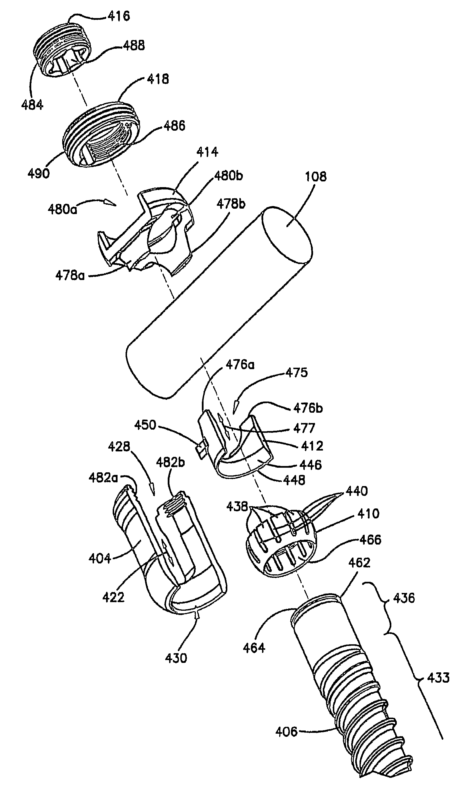
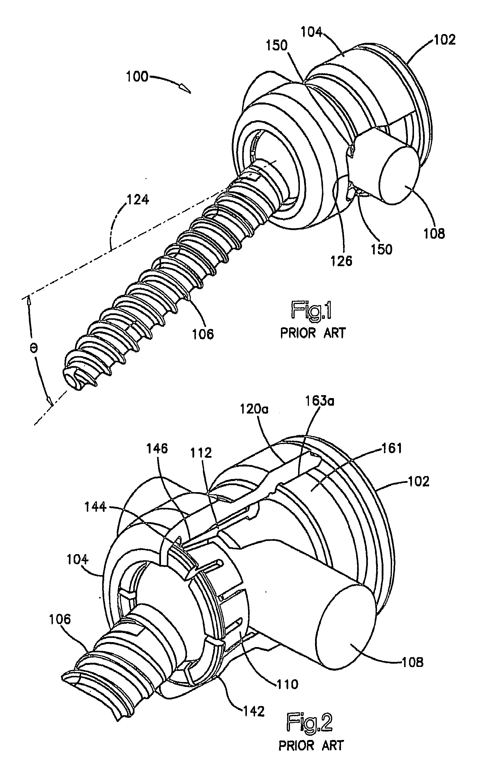
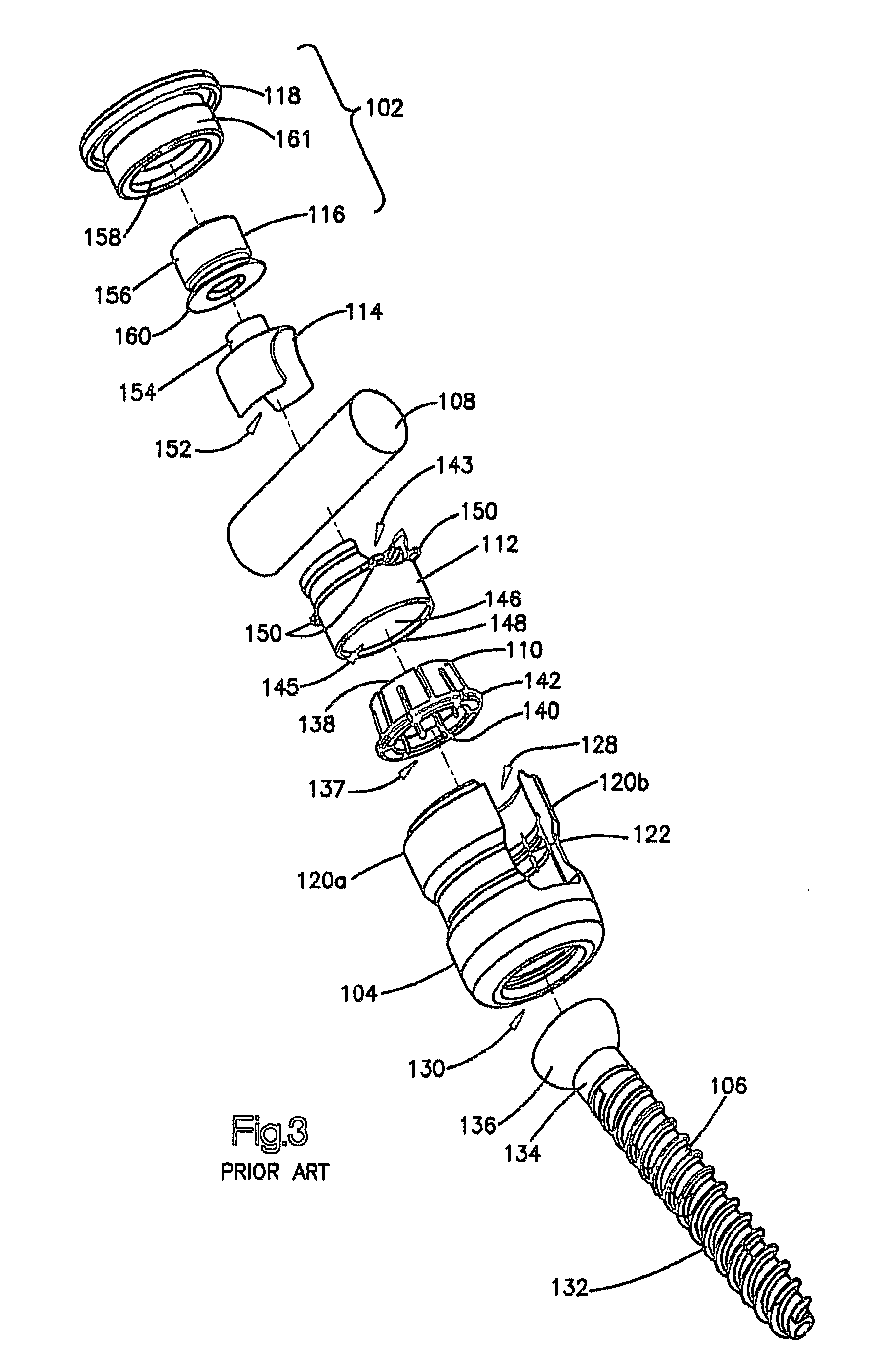
[0020]FIGS. 1-3 show a known polyaxial bone anchor. Polyaxial bone anchor 100 includes a fastener 102, an anchor head 104, and an anchor member 106. A spinal rod 108 may be clamped or locked in bone anchor 100, while anchor member 106, which may be a pedicle screw, hook, or other similar structure (and is referred to hereinafter as pedicle screw 106) may be inserted into or attached to bone. Bone anchor 100 may also include a locking element 110, ...


PUM


Abstract

A polyaxial bone anchor has a headless anchor member (e.g., a screw, hook, or other structure for attaching to bone) that allows the size of the bone anchor to be small. A locking element securely snap-fits over the headless anchor member such that inadvertent separation from the anchor member is unlikely. When the anchor member is attached to the locking element and the locking element is seated within the anchor head of the bone anchor, the headless anchoring member can polyaxially rotate about a central axis of the bone anchor before being locked in place.

Description

TECHNICAL FIELD OF THE INVENTION[0001]This invention relates to bone fixation devices and related methods of fixation. More particularly, this invention relates to polyaxial bone anchors having headless screws and hooks, and more specifically, polyaxial pedicle screws and hooks, for use in, for example, the fixation of the spine.BACKGROUND OF THE INVENTION[0002]Polyaxial bone anchors and methods of use in treating spinal disorders are known. Typical methods involve anchoring at least two screws or hooks into the vertebrae, and fixing the screws or hooks along a spinal rod to position or immobilize the vertebrae with respect to one another. The screws or hooks (referred to hereinafter as anchor members) commonly have anchor heads with U-shaped channels in which the spinal rod is inserted and subsequently clamped by a fastener, such as, for example, a threaded nut, set screw, or locking cap. These methods commonly involve multiple anchor members and multiple spinal rods. The spinal ro...

Claims


Application Information

Patent Timeline
Patent Type & Authority Applications(United States)
IPC IPC(8): A61B17/70A61B17/86
CPCA61B17/7037A61B17/7032
Inventor ASCHMANN, FELIX
Owner DEPUY SYNTHES PROD INC
Why Eureka
Try Eureka