Monitoring, predicting and treating clinical episodes

Inactive Publication Date: 2008-11-06
EARLYSENSE
View PDF101 Cites 533 Cited by
  • Summary
  • Abstract
  • Description
  • Claims
  • Application Information

AI Technical Summary

Benefits of technology

[0099]Embodiments of the present invention provide methods and systems for monitoring patients for the occurrence or recurrence of a physiological event, for example, a chronic illness or ailment. This monitoring assists the patient or healthcare provider in treating the ailment or mitigating the effects of the ail

Problems solved by technology

For example, some chronic diseases interfere with normal breathing and cardiac processes during wakefulness and sleep, causing abnormal breathing and heartbeat patterns.
Breathing and heartbeat patterns may be modified via various direct and indirect physiological mechanisms, resulting in abnormal patterns related to the cause of modification.
Asthma management presents a serious challenge to the patient and physician, as preventive therapies require constant monitoring of lung function and corresponding adaptation of medication type and dosage.
However, monitoring of lung function requires sophisticated instrumentation and expertise, which are generally not available in the non-clinical or home environment.
The efficacy of aerosol type therapy is highly dependent on patient compliance, which is difficult to assess and maintain, further contributing to the importance of lung-function monitoring.
Early treatment at the pre-episode stage may reduce the clinical episode manifestation considerably, and may even prevent the transition from the pre-clinical stage to a clinical episode altogether.
Efficient asthma management requires daily monitoring of respiratory function, which is generally impractical, particularly in non-clinical or home environments.
However, these monitoring devices have limited predictive value, and are used as during-episode markers.
In addition, peak-flow meters and nitric-oxide monitors require active participation of the patient, which is difficult to obtain from many children and substantially impossible to obtain from infants.
In most cases, it is the left side of the heart which fails, so that it is unable to efficiently pump blood to the systemic circulation.
The ensuing fluid congestion of the lungs results in changes in respiration, including alterations in rate and/or pattern, accompanied by increased difficulty in breathing and tachypnea.
W

Method used


Image

  • Monitoring, predicting and treating clinical episodes
  • Monitoring, predicting and treating clinical episodes
  • Monitoring, predicting and treating clinical episodes

Examples


example 1

[0884]Sensor A receives a compound signal comprised of a superposition of a signal s(t) and noise e(t): x(t)=s(t)+e(t).

[0885]Sensor B receives a projection of the noise denoted e′(t).

[0886]For this example, assume that Signal s(t) and noise e(t) are uncorrelated. The signal s(t) is extracted via adaptive elimination of a reconstructed noise signal from the compound signal plus noise x(t) received by sensor A, by minimizing the mean-square difference: MIN {[[s(t)+e(t)]−h(t)*e′(t)]̂2}, wherein h(t) denotes the impulse response of a linear time-invariant (LTI) filter.

[0887]Solving for h(t) yields the desired solution: s(t)=x(t)−h(t)*e′(t).

example 2

[0888]Sensors A and B receive different projections of a compound signal comprised of a superposition of a signal s(t) and noise e(t). For this example, assume that:

[0889]signal x(t) and noise e(t) are uncorrelated; and

[0890]signal and / or noise spectrum are known.

[0891]The axes are rotated to enhance signal and / or noise projections, until the desired characteristic spectrum is achieved, as follows (alpha and beta are incidence angles of the signal and noise, respectively):

Sensor A reads: S1(t)=x(t)*sin(alpha)+e(t)*sin(beta)

Sensor B reads: S2(t)=x(t)*cos(alpha)+e(t)*cos(beta)

[0892]The axes are rotated by gamma degrees, yielding:

S1′(t)=S1(t)*cos(gamma)+S2(t)*sin(gamma)

S2′(t)=S1(t)*sin(gamma)+S2(t)*cos(gamma)

[0893]The rotated signals S1′(t) and S2′(t) are calculated for all angles until noise contribution is cancelled (when gamma=pi-beta), and a scaled version of the desired signal is obtained:

S1’(t)=[x(t)*sin(alpha)+e(t)*sin(beta)]*cos(gamma)+[x(t)*cos(alpha)+e(t)*cos(beta)]*sin(gamma...

example 3

[0894]Identical sensors A and B are placed in close proximity and at the same orientation. Both sensors receive a superposition of near field signals and far field noise.

[0895]For this example, assume that:[0896]the distance between the sensors is significantly smaller than their distance from the noise source, but is of the order of magnitude of the distance from the signal source; and[0897]the signal source is comprised of a superposition of at least two differently oriented signal sources. For simplicity, the following description assumes two signal sources.

[0898]Let x1(t) and x2(t) denote the two near field signal sources.

[0899]Let e(t) denote the far field noise signal.

Sensor A reads: S1(t)=x1(t)+e(t)

Sensor B reads: S2(t)=x2(t)+e(t)

[0900]Then the difference signal is:

Sdiff=S1(t)-S2(t)=x1(t)-x2(t)+e(t)-e(t)=X1(t)-x2(t)

[0901]Thus, the far field signal is suppressed.


PUM


Abstract

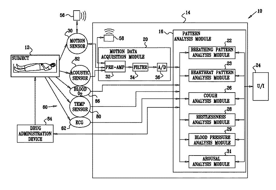
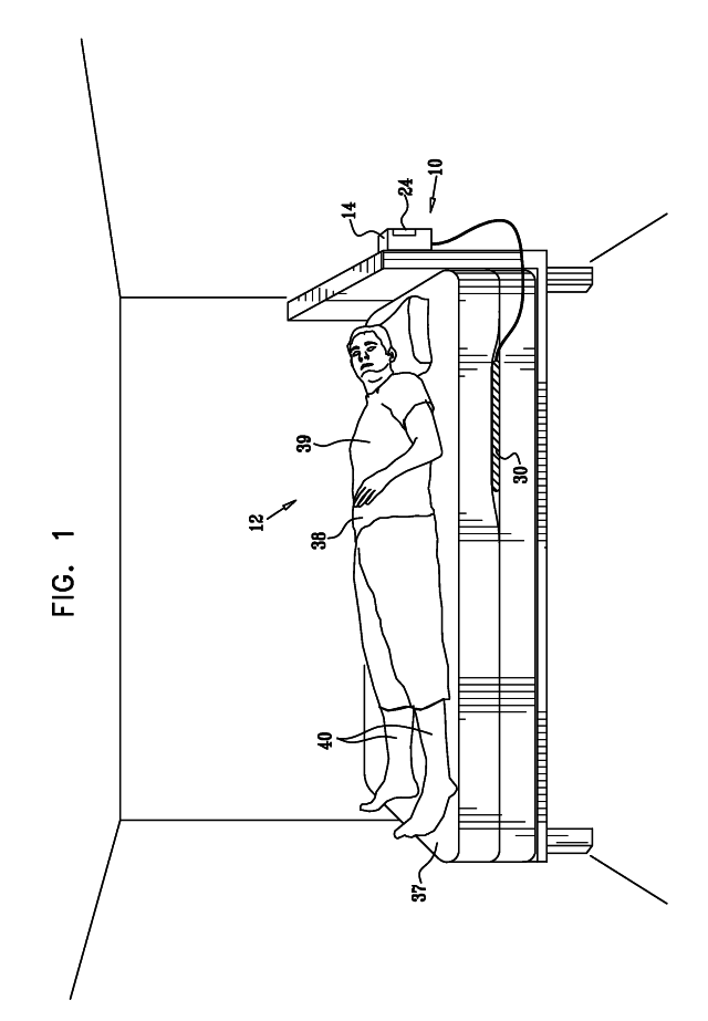
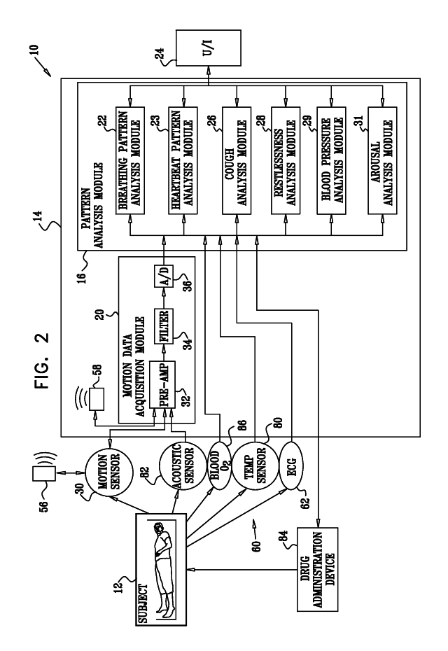
Apparatus (10) is provided that includes at least one sensor (30), configured to sense a physiological parameter of a subject (12) and to sense large body movement of the subject (12), an output unit (24), and a control unit (14). The control unit (14) is configured to monitor a condition of the subject (12) by analyzing the physiological parameter and the sensed large body movement, and to drive the output unit (24) to generate an alert upon detecting a deterioration of the monitored condition. Other embodiments are also described.

Description

CROSS-REFERENCES TO RELATED APPLICATIONS[0001]The present application claims the benefit of the following US provisional patent applications, all of which are assigned to the assignee of the present application and are incorporated herein by reference:[0002]U.S. Provisional Application 60 / 924,181, filed May 2, 2007;[0003]U.S. Provisional Application 60 / 924,459, filed May 16, 2007;[0004]U.S. Provisional Application 60 / 935,194, filed Jul. 31, 2007;[0005]U.S. Provisional Application 60 / 981,525, filed Oct. 22, 2007;[0006]U.S. Provisional Application 60 / 983,945, filed Oct. 31, 2007;[0007]U.S. Provisional Application 60 / 989,942, filed Nov. 25, 2007;[0008]U.S. Provisional Application 61 / 028,551, filed Feb. 14, 2008; and[0009]U.S. Provisional Application 61 / 034,165, filed Mar. 6, 2008.[0010]The present application is related to an international patent application entitled, “MONITORING, PREDICTING AND TREATING CLINICAL EPISODES,” filed on even date herewith, which is incorporated herein and ...

Claims


Application Information

Patent Timeline
IPC IPC(8): A61B5/02
CPCA61B5/0205A61B5/024A61B5/0823A61B5/1116A61B5/1118A61B5/113A61B5/1455A61B5/412A61B5/445A61B5/447A61B5/4818A61B5/6887A61B5/6892A61B5/7207A61B5/7285A61B5/746A61B5/7264A61B5/7282A61B2562/043
Inventor HALPERIN, AVNERTSOREF, LIATGROSS, YOSEFLANGE, DANIEL H.BEN-ARI, JOSEF H.AVERBOUKH, ARKADITODROS, KOBYKARASIK, ROMANMEGER, GUYZIEHERMAN, YEHUDA
Owner EARLYSENSE
Why Eureka
Try Eureka