Ergonomic systems and methods providing intelligent adaptive surfaces and temperature control

a technology of adaptive surfaces and ergonomic systems, applied in the direction of contraceptive devices, light and heating devices, laminated elements, etc., can solve the problems of increasing contact patches, causing medical problems, and increasing the number of contact patches

Inactive Publication Date: 2001-05-15
PROMDX TECH
View PDF411 Cites 495 Cited by
  • Summary
  • Abstract
  • Description
  • Claims
  • Application Information

AI Technical Summary

Benefits of technology

The present invention provides a number of different ergonomic intelligent adaptive surface and thermal control embodiments, providing comfort, cooling and/or heating functions. These include cryotherapy, garm

Problems solved by technology

The theory of intelligent adaptive surfaces provides that too high a pressure applied to an area of skin may cause discomfort or produce medical problems.
Actuators, provided under the surface, deform the surface to adjust the applied pre

Method used


Image

  • Ergonomic systems and methods providing intelligent adaptive surfaces and temperature control
  • Ergonomic systems and methods providing intelligent adaptive surfaces and temperature control
  • Ergonomic systems and methods providing intelligent adaptive surfaces and temperature control

Examples


example 2

CRYOTHERAPY SYSTEM INJECT VALVE

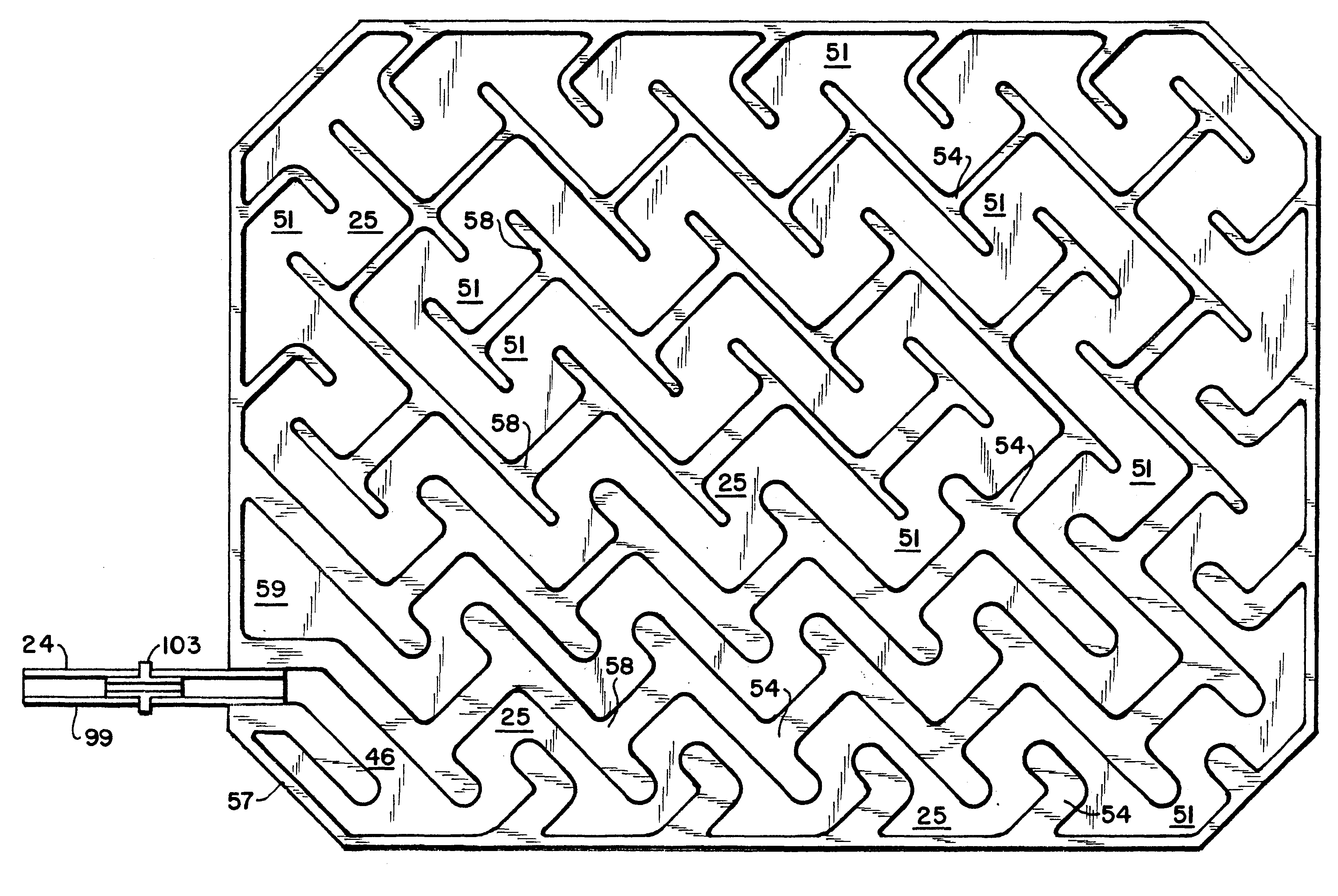
The inject valve 3 according to the present invention mates to the canister adapter 2, providing a sealed path from the canister valve 15, through the inject valve 3, to a piece of tube 24 which connects the inject valve 3 to the heat transfer portion of the cryotherapy device 16. Thus, the inject valve body 31 mates to the 1 / 2 turn interrupted screw thread 9, and connects easily. The 1 / 2 turn thread 9 causes the inject valve 3 to move axially toward the canister 1, and locks in place. The inject valve 3 includes a hollow cylindrical central post 12 which protrudes downward, concentric and outside the valve stem 4 of the canister 1. The stem or central cylindrical post 12 of the inject valve 3 depresses the valve stem 4 of the canister 1, releasing its contents, the refrigerant 13. An O-ring 14 provides a seal so that the refrigerant 13 does not leak around the inject valve 3.

The inject valve 3 comprises two flow paths. A first flow path provides a pre...

example 3

CRYOTHERAPY SYSTEM OVERCAP

An overcap 35 is preferably provided to prevent the inject valve pushbutton 22 from becoming lost. The overcap 35 is sealed to the inject valve body 31 by means of ultrasonic welding. The overcap 35 also includes a "V" type clip 36 which fits over the umbilical tube 24 which carries the refrigerant 13 from the inject valve 3 to the cryotherapy device 16, thereby preventing accidental disconnection of the tube 24. The retaining structure including the "V" type clip 36 also prevents catastrophic results from a kink in the tube 24 by ensuring that the flow path does not fail if the flow is temporarily blocked. The tube 24 is preferably a 1 / 8" ID Tygon.RTM. or polyurethane tube, which is inserted around a hollow stem 37 protruding from the side of the inject valve body 31.

example 4

CRYOTHERAPY SYSTEM INJECT VALVE BODY

The inject valve 3 valve body 31 includes a ball seat 38. The ball seat 38 has a number of functions. First, it retains the ball 17 which is displaced to provide the fast fill feature. Second, it holds a rubber O-ring 39 which prevents leakage when the ball 17 is seated and the fast fill feature is not activated. Third, the ball seat 38 has one or more narrow orifices 26 drilled vertically through it to provide a normal, e.g., steady state, flow path. These orifices 26 are each about 0.006" diameter, although this will vary with the refrigerant 13 mixture used and the desired flow rate. The diameter of these orifices 26 is precisely determined to control the steady state flow rate and provide a constant temperature in the maze 25. The normal flow rate is generally predetermined, and devices which require differing steady state flow rates are modified by varying the number of orifices 26 bypassing the fast fill valve ball seat 38. It is also possib...


PUM


Abstract

Ergonomic systems which provide medical therapy, comfort and enhanced function are provided. Surfaces are provided with adjustable contour, transient force damping and temperature. The technologies are applied to footwear, seating surfaces an cryotherapy devices. The cooling and cryotherapy system employ an evaporator in close proximity to skin, and therefore employ methods to reduce risk of frostbite. Advanced control and power supply options are disclosed.

Description

The present invention relates to the field of ergonomic systems, having intelligent adaptive surfaces and temperature control, for providing comfort and cryotherapy, and apparatus and methods therefore.The advantages and general design of intelligent adaptive surfaces are well known, as are various methods for implementation in particular articles, such as seating surfaces, mattresses, and the like. However, miniaturization and ruggedization of these systems remains an issue.Likewise, cryotherapy systems are also known, which facilitate healing and reduce inflammation. The combination of cryotherapy to about 4.degree. C. and controlled external pressure of about 0.4-0.8 psi has been clearly documented.In various types of athletic footwear, it is recognized that the comfort and fit of the footwear can affect the athletic performance. In order to increase both the comfort and fit of footwear, manufacturers have incorporated inflatable bladders of various designs into the construction ...

Claims


Application Information

Patent Timeline
IPC IPC(8): A61F7/10A61F7/00F28F3/00F28F3/12F28D20/02
CPCA43B1/0054A43B3/0005A43B3/0015A43B3/0026A43B7/02A43B7/04A43B7/06A43B7/14A43B7/1415A43B13/14A43B13/181A43B13/189A43B13/203A43B13/206A61F7/02A61F7/10B60N2/5621B60N2/5685B60N2/5692F28F3/12A61F2007/0002A61F2007/0027A61F2007/0029A61F2007/0039A61F2007/0058A61F2007/0076A61F2007/0225A61F2007/0233A61F2007/0295F28D20/02F28D2021/0071A43B3/38A43B3/35A43B3/34
Inventor BAILEY, SR., RICHARD F.FISHER, RONALD A.HOFFBERG, STEVEN M.
Owner PROMDX TECH
Why Eureka
Try Eureka