Boom with mast assembly

a technology which is applied in the field of boom and mast, can solve the problems of bending force, inertia opposing acceleration, and the weight of the sensors, and achieve the effect of reducing the weight of the boom and its own weigh

Inactive Publication Date: 2007-04-24
SHOOK MOBILE TECH
View PDF25 Cites 156 Cited by
  • Summary
  • Abstract
  • Description
  • Claims
  • Application Information

AI Technical Summary

Benefits of technology

[0012]The present invention provides a highly rigid, torsion-resistant, and buckle-resistant boom design, which may include a vertical portion, providing stable support for the supported load. This invention provides a horizontal boom section, and in a preferred embodiment includes a vertical boom section depending downwardly from the distal end of the horizontal boom section. In another preferred embodiment, the proximal end of the horizontal boom section is preferably mounted to a vertical support, such as an elevatable mast, permitting vertical movement of the boom / mast structure, and rotation of the boom structure.
[0015]Preferably, the boom further includes a vertical boom section, including a set of continuous tubes, or rods, which run the height of the vertical boom section, and penetrate several flanges arrayed along its height. The several flanges are substantially perpendicular to the vertical, and preferably congruent to inward-facing C-channel sections. The C-channel sections run the height of the vertical boom section, and are joined to the flanges. In a particularly preferred embodiment, a joint is provided roughly in the middle of the vertical boom section, permitting the lower segment to be folded upwardly against the upper segment, reducing the overall length of the vertical boom section for ease of stowage.
[0016]In a preferred embodiment, in order to facilitate elevation and rotation of the boom relative to a mobile transport, a mast-head and mast assembly are provided. The horizontal boom section, to which the vertical boom section is preferably mounted, is mounted to a mast-head, which is itself mounted to a mast assembly. The mast assembly is mounted to the chassis of the mobile transport. A mast assembly includes a mast guide and an elevation system to elevate the mast and the boom structure supported thereby. The mast-head is mounted to the top of the mast assembly, facilitating joinder of the horizontal boom section to the mast. The mast-head includes a rotation drive for rotating the boom structure. A counterweight structure may also be mounted to the mast-head, opposing the torque created by the weight of the boom structure.
[0017]The mast is preferably rigid, resistant to torque, and transmits out-of-vertical forces to the chassis without adversely affecting operation of the elevation system. In a preferred embodiment, a composite mast, formed of a two-by-two square grouping of hollow square-section tubes provides such rigidity and strength. The mast assembly further preferably includes a guide for the mast, which includes four similar hollow square-section tubes fixed to the chassis outwardly of the corners of the mast, and rollers between the mast corners and the inner corners of the guide. Preferably, several sets of rollers are positioned at varying heights along the mast. The rollers permit translation of the mast relative to the guide, which is fixed to the chassis, but transmit to that chassis the forces out of the vertical, created by torque of the weight of a boom or load. The elevation system also preferably includes a screw and a screw jack, which require little power for operation and are very reliable. This system has advantages over alternatives, such as a hydraulic lift for a similar mast, or a mast formed of a hydraulic piston. The weight and cost of an additional latching system are avoided by using the screw jack system, which does not depend upon a hydraulic power source for lift, and can maintain position without power input. The present invention also avoids compression and failure of hydraulic seals by omitting them and transmitting any lateral loads via rollers, which are designed to transmit this load to the guide.

Problems solved by technology

For instance, forward acceleration of the mobile inspection unit, and the resistance to motion of the boom structure, will result in inertia opposing that acceleration.
Other sources of torsional effects include wind resistance and accidental obstruction of the boom structure.
Similarly, bending forces are present resulting from the weight of the sensors and the boom's own weight.

Method used


Image

  • Boom with mast assembly
  • Boom with mast assembly
  • Boom with mast assembly

Examples


Embodiment Construction

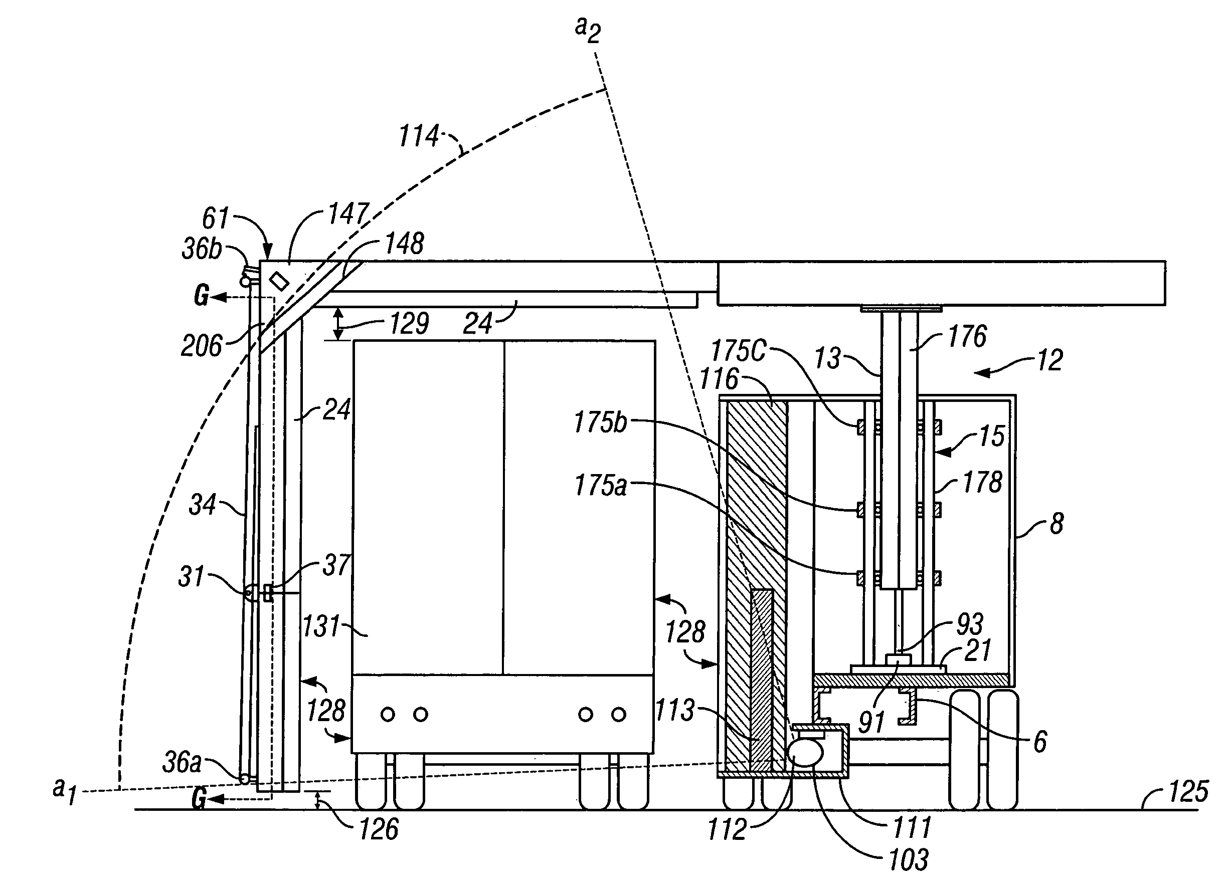
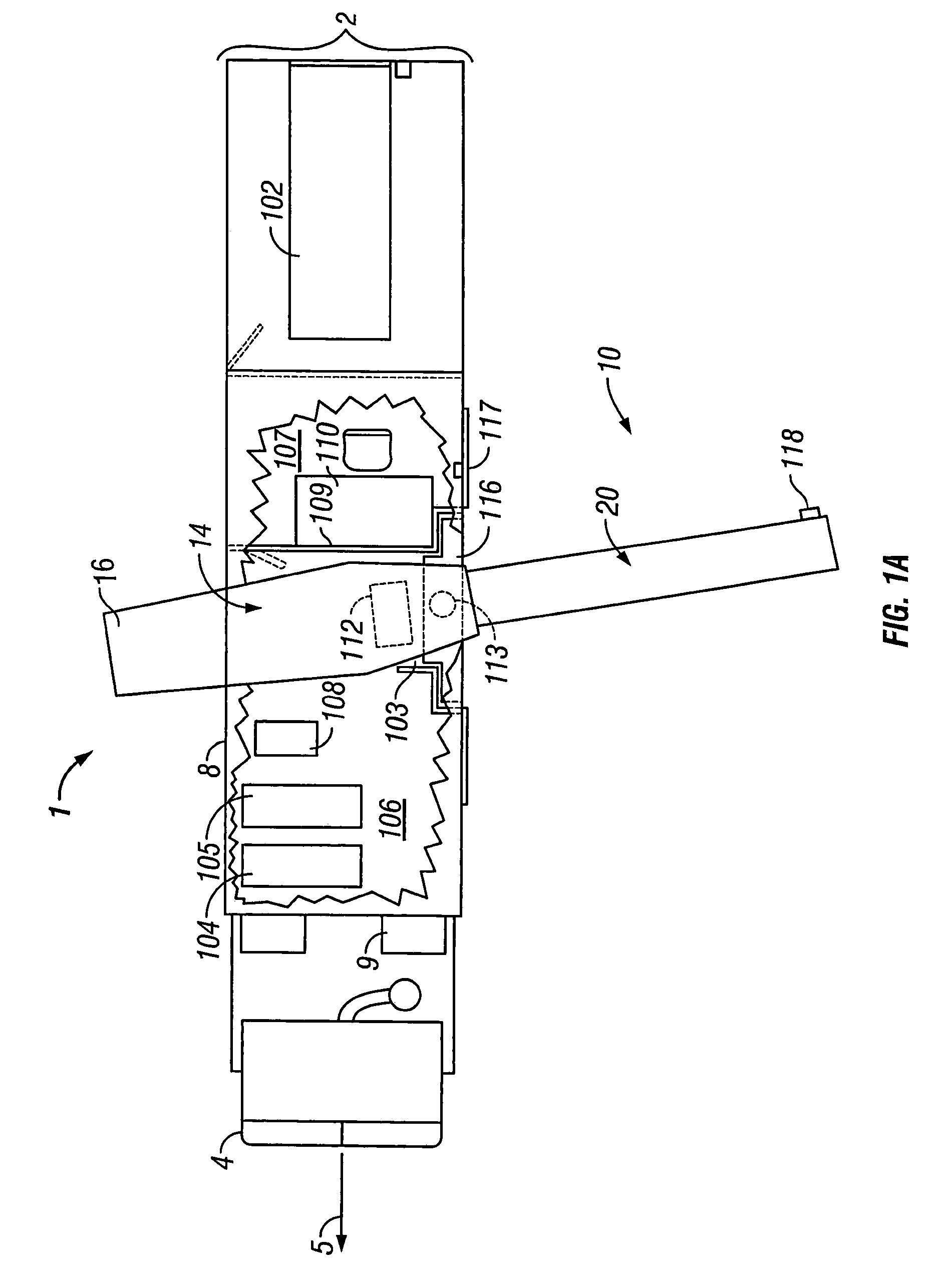
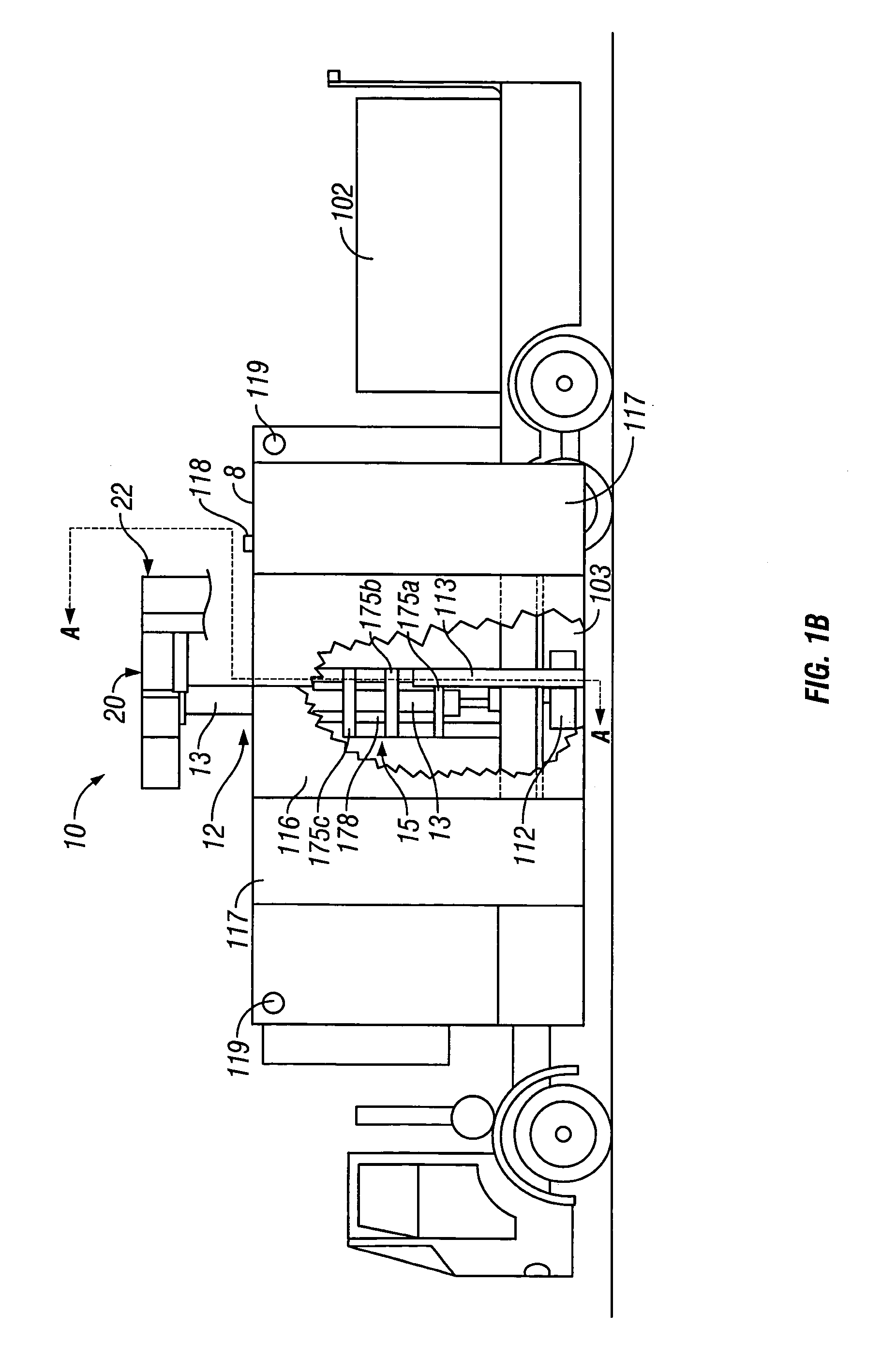
[0052]Referring now to the accompanying figures, and in particular to FIGS. 1A–1D, a specific preferred embodiment of the present invention is depicted as mobile inspection unit 1 including instrument boom 10. Instrument boom 10 includes horizontal boom section 20, vertical boom section 22; sensor packages 24, and associated mast assembly 12. Mast assembly 12, mounted on chassis 6 of mobile transport 2, includes mast 13, mast-head 14, mast guide 15, counter-weight 16 and turntable bearing 17.

[0053]Referring also to FIG. 2B, mobile inspection unit 1 may be self-propelled and operated from cab 4, or may incorporate an independent tractor (not depicted). Inspection unit 1 moves along movement axis 5 (FIG. 1A), normally also the longitudinal axis of the unit. Mobile inspection unit 1 includes mobile transport 2, which will ordinarily have a conventional main drive system 3, suitable for propelling mobile inspection unit 1 on ordinary roads or highway systems. Drive system 3 may include ...


PUM


Abstract

A torsion- and bending resistant boom formed of beams running the length of the structure, a set of pierced, transverse flanges arrayed along, and substantially perpendicular to, the length of the structure, a continuous longitudinal member running the length of the structure, piercing the flanges, and several further longitudinal members, outward of the first member. The longitudinal members are welded to the flanges. An elevatable mast assembly raises and lowers the boom, and has a mast and guides formed of hollow tubes, and rollers between the guides and the mast, the rollers transferring torque loading to the guides.

Description

RELATED APPLICATION[0001]This application is a divisional of U.S. patent application Ser. No. 09 / 451,830 filed Nov. 30, 1999 now U.S. Pat. No. 6,763,635, entitled “Improved Boom with Mast Assembly.”BACKGROUND OF THE INVENTIONField of the Invention[0002]The present invention relates to booms and mast structures for supporting a load, and to those supporting torque-inducing loads. In particular, if relates to a boom structure that may be rotated, and a mast structure that may be elevated. More particularly, it relates to a boom and mast structure mounted on a mobile platform for deployment of a system for inspection of vehicles or containers.[0003]A boom used to support a load at a distance from a vertical support must resist deformation resulting from the downward forces applied thereto by that load, and the torque created thereby. In addition, where that boom and load may be subject to acceleration resulting from translation or rotation, or other application of forces, in other than...

Claims


Application Information

Patent Timeline
Patent Type & Authority Patents(United States)
IPC IPC(8): H05G1/02B60P1/54B66C23/18B66F11/04
CPCB60P1/5433B66C17/06B66C23/18B66F11/046G01V5/0016
Inventor LOWMAN, ERIC E.
Owner SHOOK MOBILE TECH
Why Eureka
Try Eureka