
Electrical surgical instrument with optimized power supply and drive

Active Publication Date: 2007-11-22
CILAG GMBH INTERNATIONAL
View PDF12 Cites 464 Cited by
  • Summary
  • Abstract
  • Description
  • Claims
  • Application Information

AI Technical Summary

Benefits of technology

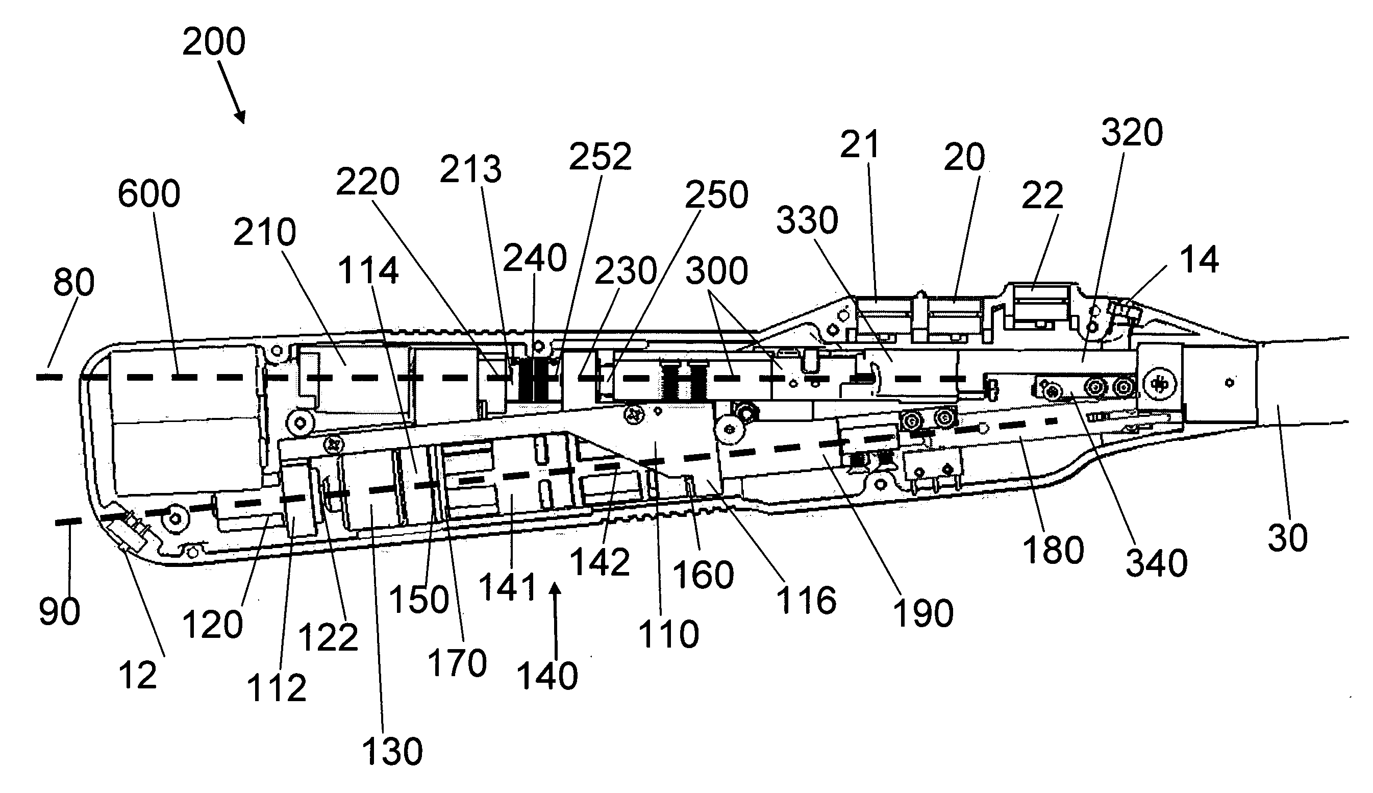
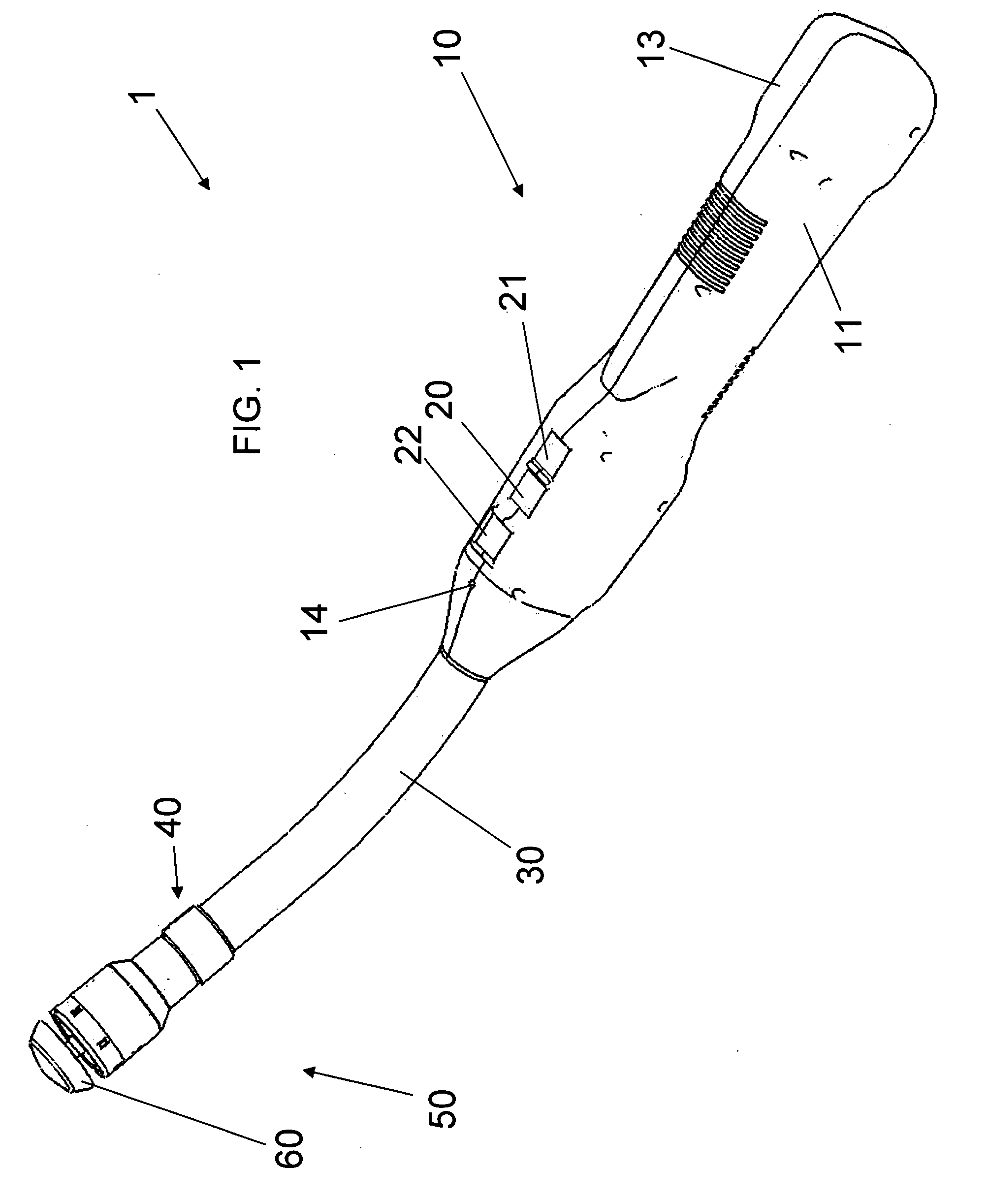
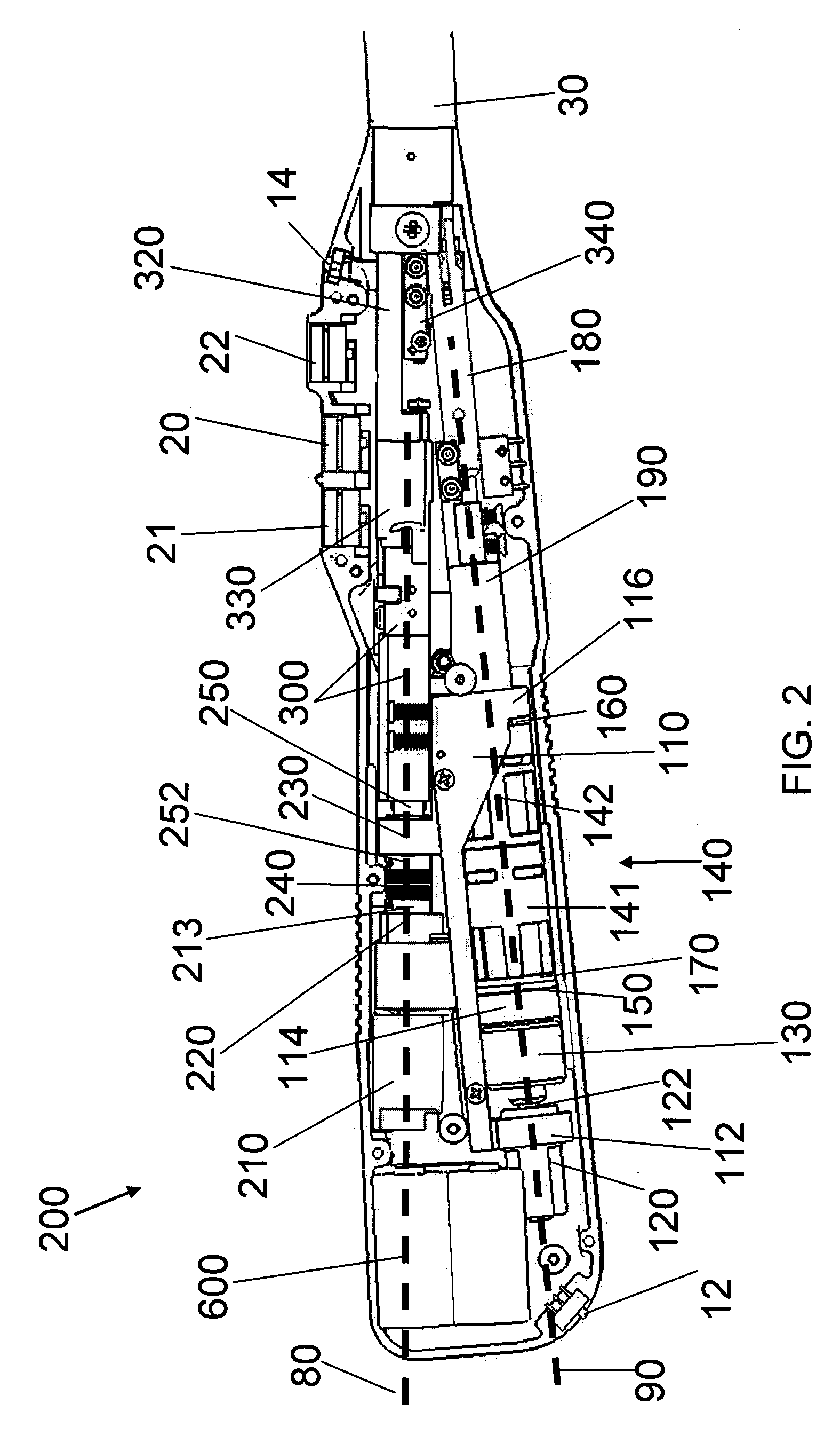
[0008]An offset-axis configuration for the two anvil and staple firing sub-assemblies creates a device that can be sized to comfortably fit into a user's hand. It also decreases manufacturing difficulty by removing previously required nested (co-axial) hollow shafts. With the axis of the anvil sub-assembly being offset from the staple firing sub-assembly, the length of the threaded rod for extending and retracting the anvil can be decreased by approximately two inches, thereby saving in manufacturing cost and generating a shorter longitudinal profile.

Problems solved by technology

It also decreases manufacturing difficulty by removing previously required nested (co-axial) hollow shafts.

Method used


Image

  • Electrical surgical instrument with optimized power supply and drive
  • Electrical surgical instrument with optimized power supply and drive
  • Electrical surgical instrument with optimized power supply and drive

Examples


Embodiment Construction

[0061]Aspects of the invention are disclosed in the following description and related drawings directed to specific embodiments of the invention. Alternate embodiments may be devised without departing from the spirit or the scope of the invention. Additionally, well-known elements of exemplary embodiments of the invention will not be described in detail or will be omitted so as not to obscure the relevant details of the invention.

[0062]Before the present invention is disclosed and described, it is to be understood that the terminology used herein is for the purpose of describing particular embodiments only and is not intended to be limiting. It must be noted that, as used in the specification and the appended claims, the singular forms “a,”“an,” and “the” include plural references unless the context clearly dictates otherwise.

[0063]While the specification concludes with claims defining the features of the invention that are regarded as novel, it is believed that the invention will b...


PUM

PropertyMeasurementUnit
Lengthaaaaaaaaaa
Lengthaaaaaaaaaa
Timeaaaaaaaaaa

Abstract

A surgical instrument includes an end effector having an actuator effecting a surgical procedure when actuated, an electric motor operating the actuator, and a power supply actuating the actuator when power is supplied to the motor. The power supply has a battery cell with a given rated power for an operating period of over 15 seconds and for a total aggregate operating time of over 300 seconds. The motor and power supply are configured to utilize the battery cell at a power greater than the given rated power. The motor characteristics are selected to utilize the battery cell for periods of operation of less than 16 seconds and for a total aggregate operating time of less than 300 seconds. A one-handed handle contains all of the power supply, at least part of an anvil control assembly, and at least part of an electrically-powered stapler / cutter control assembly.

Description

CROSS-REFERENCE TO RELATED APPLICATION[0001]This application claims the priority, under 35 U.S.C. § 119, of U.S. Provisional Patent Application Ser. Nos. 60 / 801,989 filed May 19, 2006, 60 / 810,272, filed Jun. 2, 2006, and 60 / 858,112, filed Nov. 9, 2006, and is a divisional of the concurrently filed application having Attorney Docket “Elec Stapler Batt,” the entire disclosures of which are all hereby incorporated herein by reference in their entireties.STATEMENT REGARDING FEDERALLY SPONSORED RESEARCH OR DEVELOPMENT[0002]n / aFIELD OF THE INVENTION[0003]The present invention lies in the field of surgical instruments, in particular but not necessarily, stapling devices. The stapling device described in the present application is a hand-held, fully electrically powered and controlled surgical stapler.BACKGROUND OF THE INVENTION[0004]Medical stapling devices exist in the art. Ethicon Endo-Surgery, Inc. (a Johnson & Johnson company; hereinafter “Ethicon”) manufactures and sells such stapling...

Claims


Application Information

Patent Timeline
IPC IPC(8): A61B17/03
CPCA61B2019/464A61B2017/00017A61B17/1114A61B2017/00734A61B2019/302A61B17/115A61B17/068A61B2017/00398A61B2090/032A61B2090/064A61B17/1155A61B17/07207A61B17/072A61B2017/07285A61B90/03A61B2017/07257A61B2017/07271A61B2017/07278A61B2017/00115A61B2017/00477
Inventor SMITH, KEVIN W.BALES, THOMASDEVILLE, DEREK DEERIVERA, CARLOSPALMER, MATTHEW A.
Owner CILAG GMBH INTERNATIONAL
Learn More