Electrically Powered Surgical Instrument with Manual Release
What is AI technical title?
AI technical title is built by Patsnap AI team. It summarizes the technical point description of the patent document.
a surgical instrument and electric technology, applied in the field of surgical instruments, can solve problems such as reducing manufacturing difficulty
Active Publication Date: 2021-01-28
CILAG GMBH INT
View PDF0 Cites 0 Cited by
Summary
Abstract
Description
Claims
Application Information
AI Technical Summary
This helps you quickly interpret patents by identifying the three key elements:
Problems solved by technology
Method used
Benefits of technology
Benefits of technology
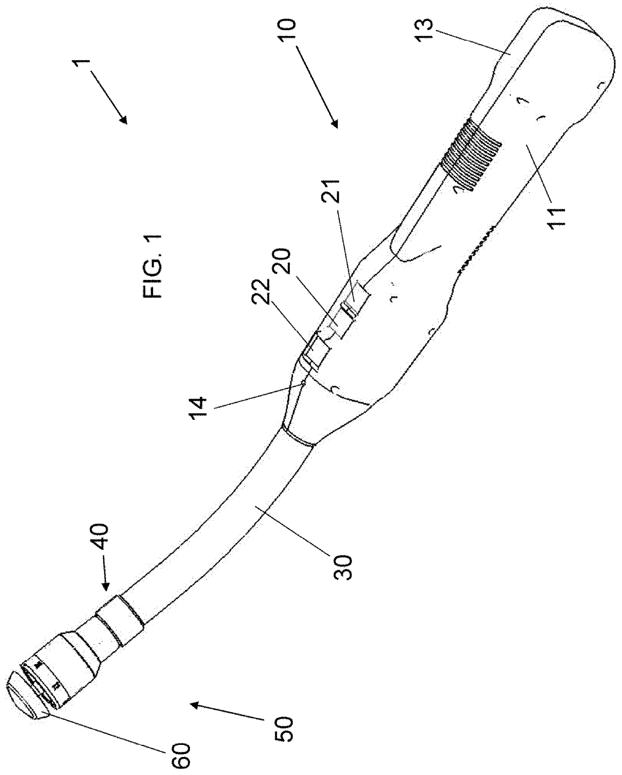
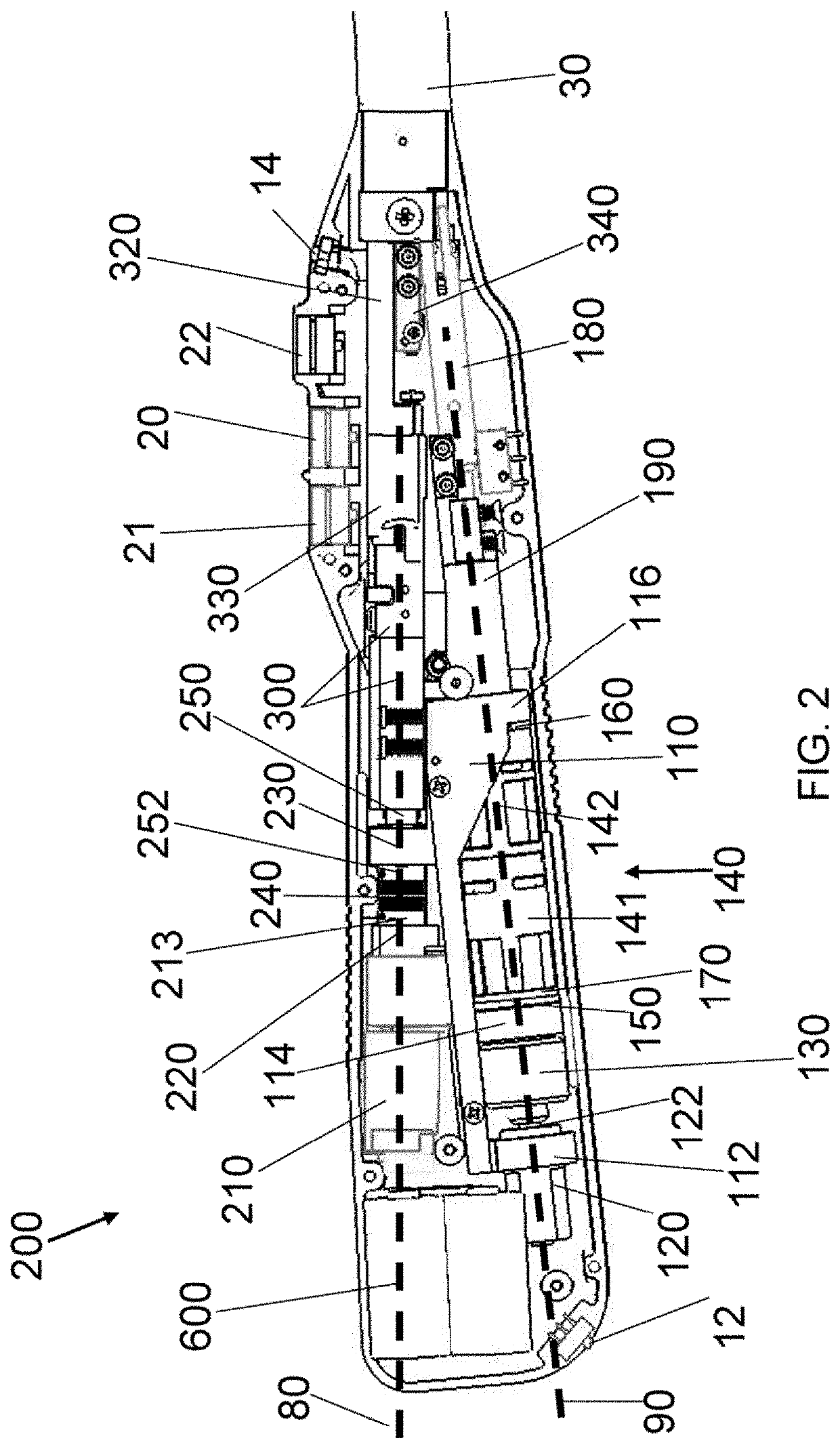
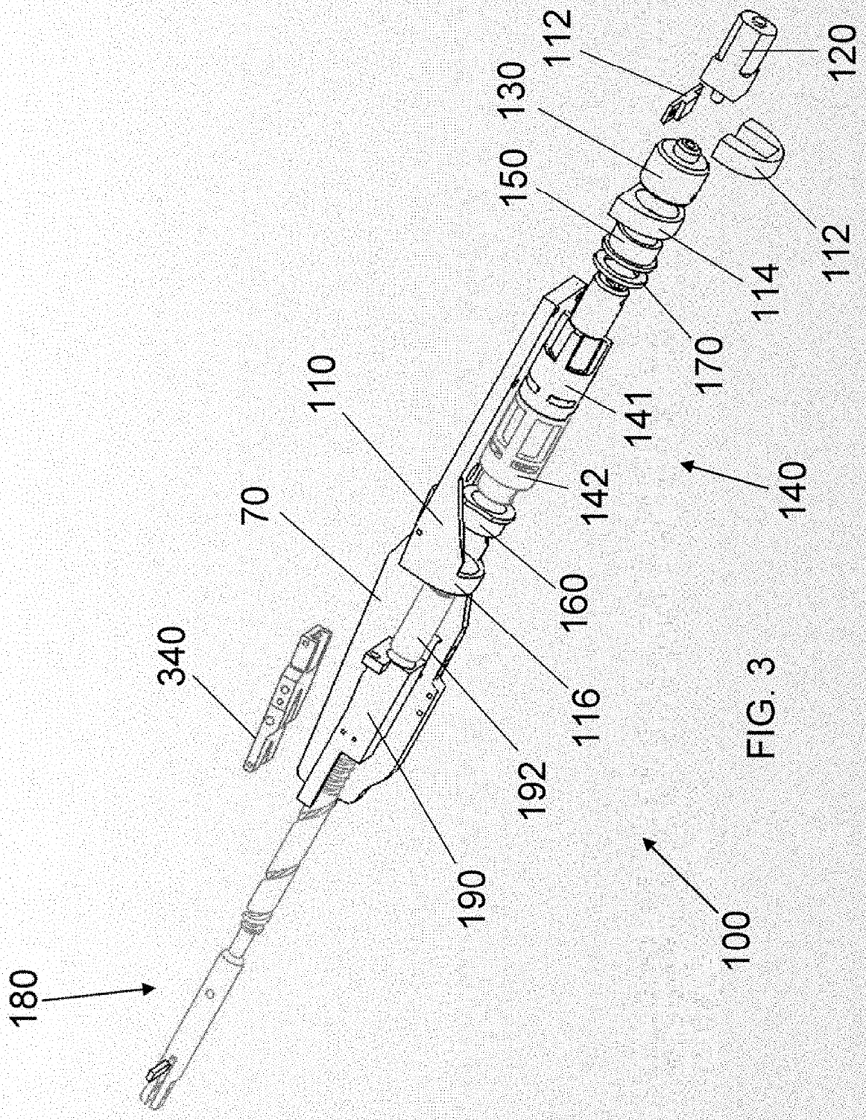
[0022]The systems, apparatuses, and methods described herein overcome the above-noted and other deficiencies of the prior art by providing a electrically self-powered surgical device that uses the self-power to effect a medical procedure. For example, in a linear endocutter, the electric on-board power can position an anvil and stapler cartridge with respect to one another about tissue to be stapled and / or cut, and, after closing the anvil and stapler cartridge with respect to one another, firing and securing the staples at the tissue (and / or cutting the tissue). Further, the electrically self-powered surgical device can indicate to the user a user-pre-defined level of compressive force being imparted upon the tissue prior to firing the staples. Also provided are methods for operating the electric surgical stapling device to staple when optimal tissue compression (OTC) exists. Further provided is a manual release device that allows recovery from a partial actuation or a jam.
[0023]An offset-axis configuration for the two anvil and staple firing sub-assemblies creates a device that can be sized to comfortably fit into a user's hand. It also decreases manufacturing difficulty by removing previously required nested (co-axial) hollow shafts. With the axis of the anvil sub-assembly being offset from the staple firing sub-assembly, the length of the threaded rod for extending and retracting the anvil can be decreased by approximately two inches, thereby saving in manufacturing cost and generating a shorter longitudinal profile.
Problems solved by technology
It also decreases manufacturing difficulty by removing previously required nested (co-axial) hollow shafts.
Method used
Image
Click on the blue label to locate the original text in one second.
Reading with bidirectional positioning of images and text.
Examples
Embodiment Construction
[0102]Aspects of the described systems, apparatuses, and methods are disclosed in the following description and related drawings directed to specific embodiments. Alternate embodiments may be devised without departing from the spirit or the scope of the invention. Additionally, well-known elements of exemplary embodiments of the invention will not be described in detail or will be omitted so as not to obscure the relevant details of the invention.
[0103]Before the systems, apparatuses, and methods are disclosed and described, it is to be understood that the terminology used herein is for the purpose of describing particular embodiments only and is not intended to be limiting. It must be noted that, as used in the specification and the appended claims, the singular forms “a,”“an,” and “the” include plural references unless the context clearly dictates otherwise.
[0104]While the specification concludes with claims defining the features of the systems, apparatuses, and methods that are r...
PUM
Abstract
A surgical device comprising a surgical end effector, an actuation assembly having a part operable to move between a first position and a second position, an electrically-powered motor, a transmission mechanically connecting the motor to the part and being operable to selectively displace the part between the first and second positions when the motor is operated, and a manual release mechanically coupled to the transmission to selectively interrupt the transmission and, during interruption, displace the part towards the first position independent of operation of the motor.
Description
CROSS-REFERENCE TO RELATED APPLICATION[0001]The present application is:[0002]a divisional of U.S. patent application Ser. No. 16 / 390,570, filed on Apr. 22, 2019, which is:[0003]divisional of U.S. patent application Ser. No. 15 / 385,385, filed on Dec. 20, 2016, now U.S. Pat. No. 10,314,583, issued on Jun. 11, 2019, which is:[0004]a continuation of U.S. patent application Ser. No. 14 / 141,563, filed on Dec. 27, 2013, now U.S. Pat. No. 9,554,803, issued on Jan. 31, 2017, which is:[0005]a divisional of U.S. patent application Ser. No. 13 / 089,041, filed on Apr. 18, 2011, now U.S. Pat. No. 8,672,951, issued on Mar. 18, 2014, which is: a divisional of U.S. patent application Ser. No. 12 / 245,017, filed on Oct. 3, 2008, now U.S. Pat. No. 7,959,050, issued on Jun. 14, 2011, which claims priority to U.S. Provisional Patent Application No. 60 / 977,489, filed on Oct. 4, 2007;[0006]a continuation-in-part of U.S. patent application Ser. No. 12 / 034,320, filed on Feb. 20, 2008, now U.S. Pat. No. 8,627,...
Claims
Application Information
Patent Timeline
Application Date:The date an application was filed.
Publication Date:The date a patent or application was officially published.
First Publication Date:The earliest publication date of a patent with the same application number.
Issue Date:Publication date of the patent grant document.
PCT Entry Date:The Entry date of PCT National Phase.
Estimated Expiry Date:The statutory expiry date of a patent right according to the Patent Law, and it is the longest term of protection that the patent right can achieve without the termination of the patent right due to other reasons(Term extension factor has been taken into account ).
Invalid Date:Actual expiry date is based on effective date or publication date of legal transaction data of invalid patent.
Patent Type & AuthorityApplications(United States)

