Locking vascular introducer assembly with adjustable hemostatic seal

a technology of vascular introducer and vascular insertor, which is applied in the direction of dilators, catheters, infusion syringes, etc., can solve the problems of affecting the insertion procedure, affecting the insertion effect,

Active Publication Date: 2007-03-20
OSCOR
View PDF37 Cites 176 Cited by
  • Summary
  • Abstract
  • Description
  • Claims
  • Application Information

AI Technical Summary

Benefits of technology

[0017]The present invention is also directed to a vascular introducer having an adjustable hemostatic seal. This embodiment of the present invention includes an elongate hollow sheath defining an axial lumen which has opposed proximal and distal end portions; a hub operatively associated with the proximal end portion of the sheath which includes a hub body portion with an axial bore in fluid communication with the axial lumen of the sheath, and a tapered proximal portion having a helical thread defined along an outer periphery thereof and a recessed channel defined circumferentially along an inner periphery thereof; an elastic annular seal disposed within the recessed channel of the hub; and a cap having an axial bore extending therethrough with a helical thread for cooperating with the helical thread of the tapered proximal portion of the hub so that rotational movement of the cap relative to the hub causes the annular seal to move radially relative to the axial bore of the hub.
[0019]In a preferred embodiment of the vascular introducer of the present invention, a trocar seal is disposed about the axial bore of the cap to prevent fluid flow from the lumen and permit insertion of devices through the axial bore of the cap.
[0020]The present invention is also directed to a vascular introducer which includes an elongated dilator having a tapered distal end portion and an axial passage extending therethrough; an elongated hollow sheath having opposed proximal and distal end portions and an axial lumen extending therethrough to accommodate the dilator; a hub operatively associated with the proximal end portion of the sheath which includes a hub body portion with an axial passage for accommodating the dilator and being in fluid communication with the axial lumen of the sheath, and a tapered proximal portion; a dilator handle associated with a proximal end of the dilator including a proximal receiving port in communication with the axial passage of the dilator and a distal mounting stem; and a locking collar having an axial bore with a proximal portion configured to receive the distal mounting stem of the dilator handle to facilitate rotation of the dilator handle and a distal portion configured to engage the tapered proximal portion of the hub.
[0023]In one embodiment of the present invention, the selectively adjustable annular seal includes a threaded portion defined on the tapered proximal portion of the hub; a circumferential recessed channel defined in an interior wall of the tapered proximal portion of the hub; an annular compressible sealing ring disposed in the circumferential recessed channel of the hub; and a sealing cap having an axial bore and a threaded portion defined therein for being threadably engaged with the threaded portion defined on the tapered proximal portion of the hub, wherein the annular compressible sealing ring in the circumferential recessed channel of the tapered proximal portion of the hub is selectively moved from a compressed position in which fluid egress through the axial passage is restricted and a decompressed position in which fluid egress through the axial passage is unrestricted by alternate threadable engagement of the sealing cap. Preferably, the sealing cap is seated within the axial bore of the locking collar such that alternate rotational movement of the locking collar effectuates the threaded engagement and disengagement of the sealing cap with the tapered proximal portion of the hub.

Problems solved by technology

This significantly complicates the insertion procedure because the introducer assembly may not slide smoothly into the blood vessel and the insertion may not be effective.
In some instances, when the dilator slides out of the sheath during insertion, the sheath may proceed completely through the vein, and break, bend, or tear.
Also, if the dilator separates from the central lumen of the sheath, blood may flow undesirably from the vessel through the sheath.
This may result in significant blood loss to the patient.
This could cause an embolism in the venous system of the patient.
This makes introduction of the lead difficult and can actually cause damage to the lead.

Method used


Image

  • Locking vascular introducer assembly with adjustable hemostatic seal
  • Locking vascular introducer assembly with adjustable hemostatic seal
  • Locking vascular introducer assembly with adjustable hemostatic seal

Examples


Embodiment Construction

[0039]In the following detailed description of the present invention, references are made to the accompanying drawings which form a part hereof, and in which is shown by way of illustration specific embodiments in which the invention may be practiced. These embodiments are described in sufficient detail to enable those skilled in the art to practice the invention, and it is to be understood that other embodiments may be utilized and that structural changes may be made without departing from the spirit and scope of the present invention. The following detailed description is, therefore, not to be taken in a limiting sense, and the scope of the present invention is defined by the appended claims and equivalents thereof.

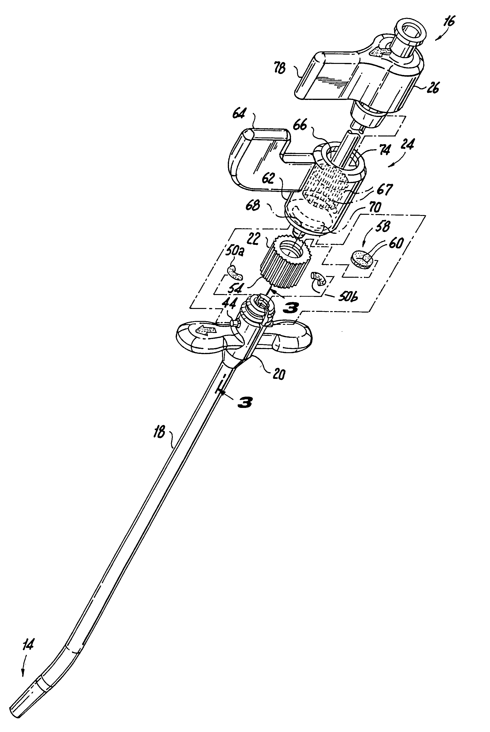
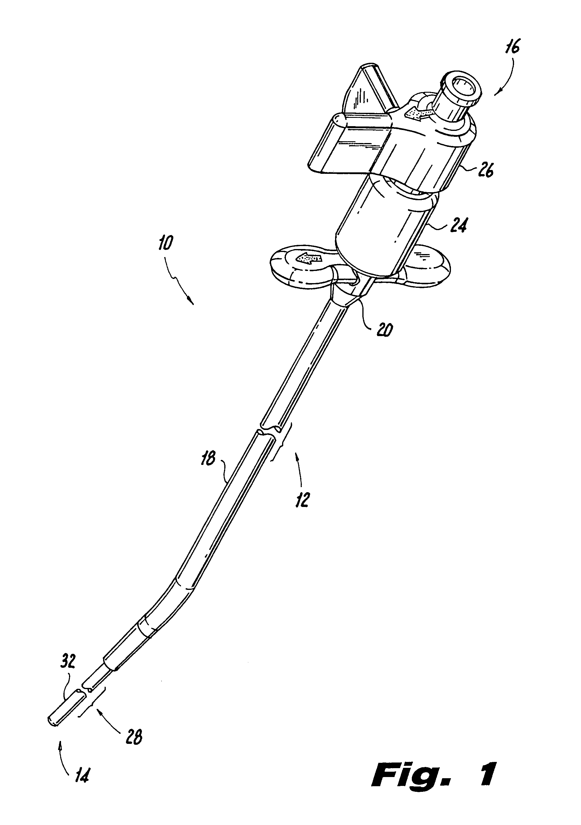
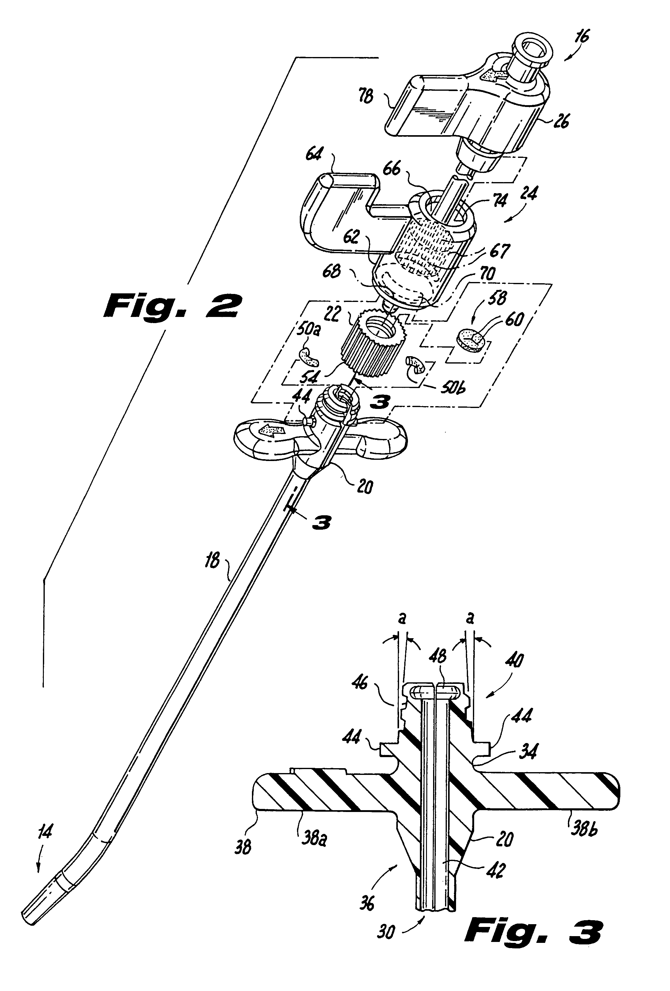
[0040]Referring now to the drawings wherein like reference numerals identify similar structural features of the invention, there is illustrated in FIG. 1, a vascular introducer assembly constructed in accordance with a preferred embodiment of the subject invention and d...


PUM


Abstract

A vascular introducer assembly is disclosed that includes a dilator, a sheath having an axial lumen for accommodating the dilator, a locking collar for securing the dilator and the sheath to one another and an adjustable hemostatic seal for preventing fluid egress from the axial lumen and restricting insertion of instruments through the axial lumen.

Description

CROSS-REFERENCE TO RELATED APPLICATION(S)[0001]The subject application claims the benefit of priority to U.S. Provisional Patent Application No. 60 / 364,649, filed Mar. 15, 2002, and U.S. Provisional Patent Application No. 60 / 391,793, filed Jun. 27, 2002, the disclosures of which are herein incorporated by reference in their entireties.BACKGROUND OF THE INVENTION[0002]1. Field of the Invention[0003]The subject disclosure relates to a vascular introducer assembly, and more particularly, to a vascular introducer assembly that includes a dilator, a sheath for accommodating the dilator, a locking mechanism for temporarily securing the dilator and the sheath to one another and an adjustable hemostatic seal for limiting fluid egress from the introducer assembly.[0004]2. Background of the Related Art[0005]The percutaneous introduction of diagnostic and / or therapeutic devices such as pacemaker leads and cardiovascular catheters into a blood vessel is typically accomplished with the aid of an...

Claims


Application Information

Patent Timeline
Patent Type & Authority Patents(United States)
IPC IPC(8): A61F11/00A61M25/06A61M39/02A61M39/06
CPCA61M25/0668A61M39/0613A61M39/0208
Inventor OSYPKA, THOMAS P.RIES, THOMAS C.DEBELLA, ERNEST G.SASS, TIMOTHY L.
Owner OSCOR
Why Eureka
Try Eureka