
Lung assist apparatus and methods for use

Inactive Publication Date: 2005-01-04
GATEWAY MEDICAL
View PDF20 Cites 313 Cited by
  • Summary
  • Abstract
  • Description
  • Claims
  • Application Information

AI Technical Summary

Benefits of technology

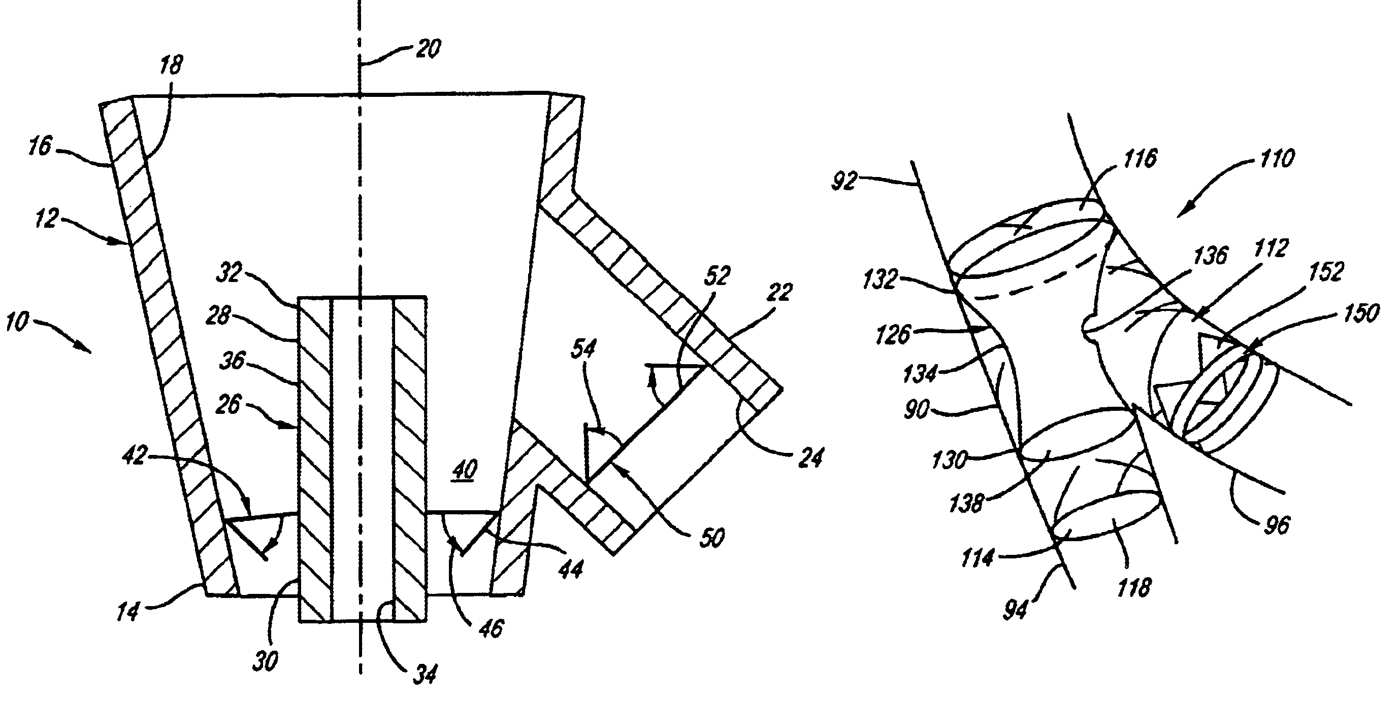
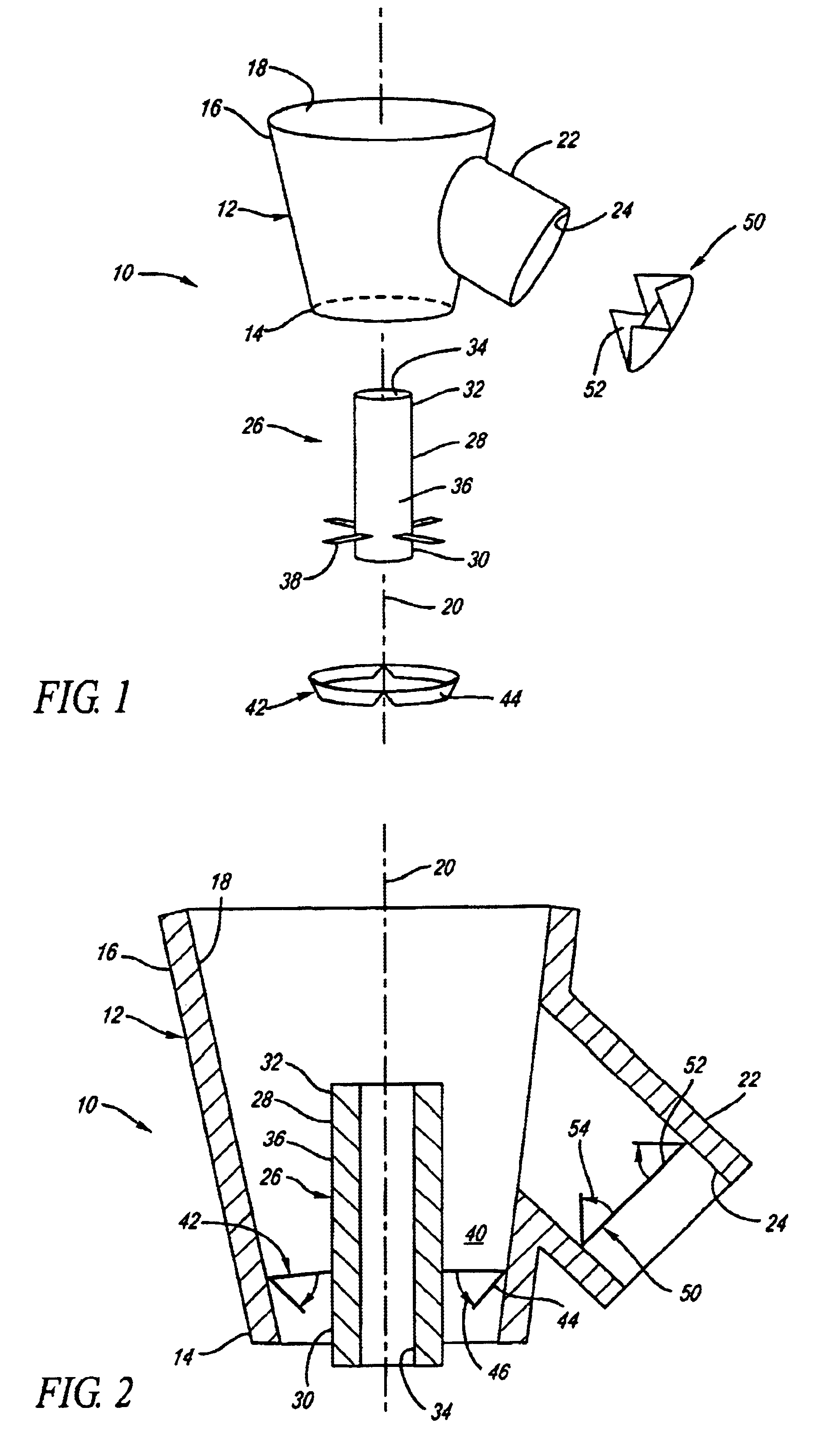
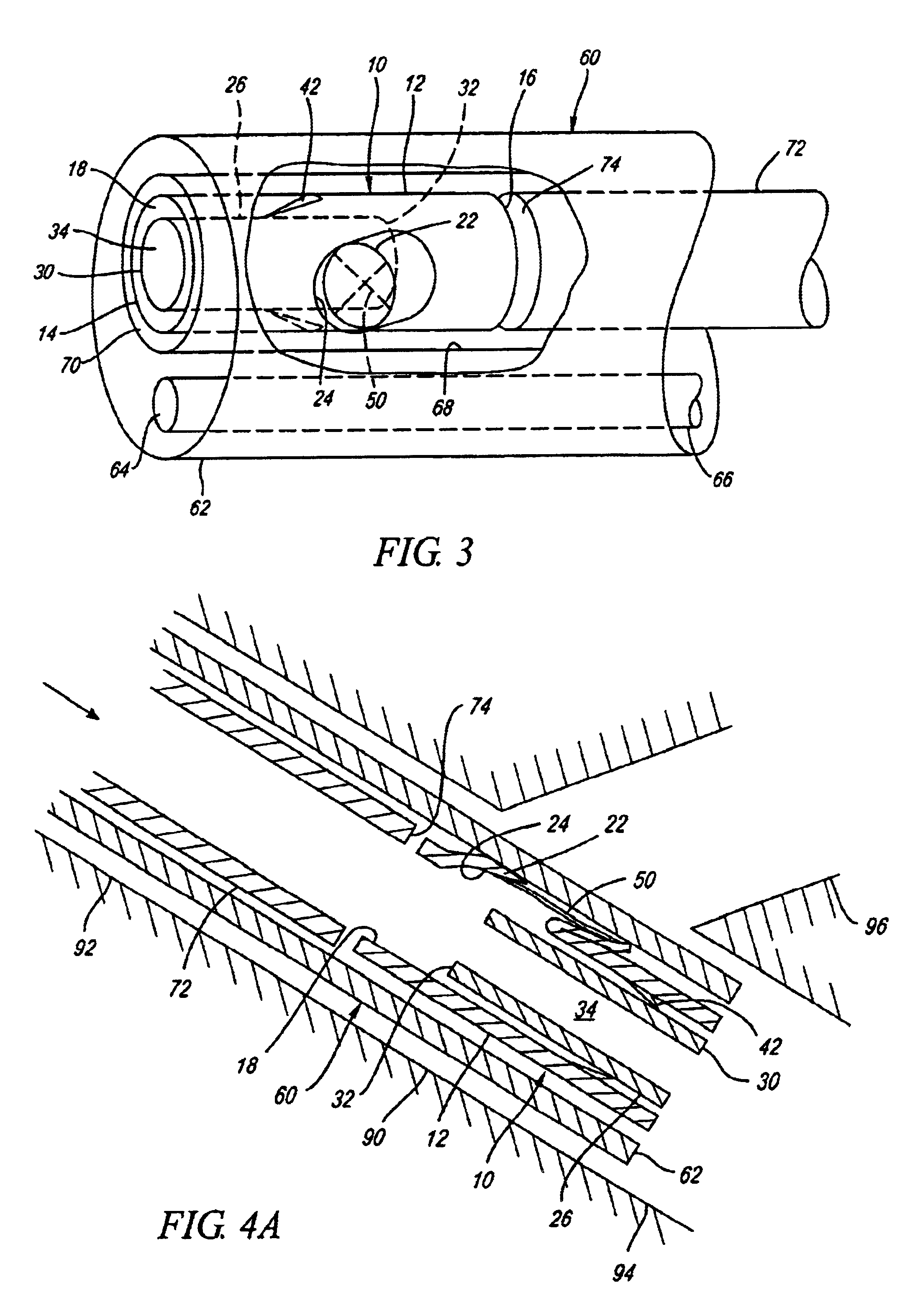
A tubular member, e.g., a nozzle, including an inlet end, an outlet end, and an inner lumen and an outer surface extending therebetween, may be carried by the support structure such that the inlet end is disposed proximate the first end, and the outlet end is disposed proximate the lateral opening. The apparatus preferably defines an outer lumen between the outer surface of the nozzle and the support structure. A first valve may be disposed across the outer lumen for controlling flow through the outer lumen in a predetermined manner. Preferably, the first valve is configured for permitting flow through the outer lumen towards the inlet end and / or for limiting flow through the outer lumen towards the outlet end. More preferably, the first valve is configured to close to prevent substantial air flow through the outer lumen towards the second end of the support structure, and cause air to pass through the inner lumen in order to exit out the second end, thereby generating a vacuum at the lateral opening.

Problems solved by technology

Patients with chronic bronchitis or other chronic occlusive pulmonary disease (“COPD”) may have reduced lung capacity and / or efficiency due to lung tissue breaking down.
For example, in severe chronic pulmonary disease, e.g., emphysema, lung tissue may be damaged or destroyed, reducing the ability of the lung to effectively transfer oxygen.
One of the problems with emphysema and like conditions is that the lungs become over-inflated, filling the chest cavity and preventing the patient from being able to inhale effectively.
LVRS, however, is an extremely invasive procedure, and exposes the patient to substantial post-operative complications.

Method used


Image

  • Lung assist apparatus and methods for use
  • Lung assist apparatus and methods for use
  • Lung assist apparatus and methods for use

Examples


Embodiment Construction

Turning now to the drawings, FIG. 1 shows a first preferred embodiment of a lung assist apparatus 10, in accordance with the present invention. Generally, the apparatus 10 includes a housing 12 or other support structure, a nozzle 26 disposed within at least a portion of the housing 12, and a first valve 42 disposed between the nozzle 26 and the housing 12. Preferably, the apparatus 10 also includes a second valve 50 that may control flow through a lateral opening 24 in the housing 12, as described further below. The components of the apparatus 10 are preferably attached to the housing 12, thereby providing a single deliverable device, although alternatively one or more of the components may be provided separately from the housing 12 and implanted in stages, as described further below.

The housing 12 includes a first end 14, a second end 16, and a lumen 18 therebetween, thereby defining a longitudinal axis 20. In a preferred embodiment, the housing 12 is a tubular body, e.g., formed ...


PUM


Abstract

A lung-assist apparatus includes a tubular housing, a tubular nozzle therein, and a first valve disposed between the housing and nozzle. The housing is implanted across a bifurcation such that the nozzle extends from a first branch communicating with a healthy region of a lung towards a main passage, and terminates proximate a lateral opening in the housing that is disposed within a second branch communicating with a damaged region of the lung. During inhalation, the first valve opens to allow air flow into the first branch, and closes during exhalation to force air through the nozzle, thereby inducing a vacuum for drawing air from the damaged region. A second valve in the second branch opens during exhalation to draw air from the diseased region, and closes during inhalation to prevent air from being drawn into the damaged region.

Description

FIELD OF THE INVENTIONThe present invention relates generally to apparatus and methods for treating chronic occlusive pulmonary disease, and more particularly to apparatus and methods for enhancing or assisting breathing, particularly exhalation from one or more regions of a lung using exhalation from a healthier region of the lung.BACKGROUNDPatients with chronic bronchitis or other chronic occlusive pulmonary disease (“COPD”) may have reduced lung capacity and / or efficiency due to lung tissue breaking down. For example, in severe chronic pulmonary disease, e.g., emphysema, lung tissue may be damaged or destroyed, reducing the ability of the lung to effectively transfer oxygen. One of the problems with emphysema and like conditions is that the lungs become over-inflated, filling the chest cavity and preventing the patient from being able to inhale effectively.In severe emphysema cases, lung volume reduction surgery (“LVRS”) has been suggested to improve lung efficiency. LVRS is perf...

Claims


Application Information

Patent Timeline
IPC IPC(8): A61F2/00A61F2/06A61F2/24A61F2/04A61F2/82
CPCA61F2/00A61F2/04A61M16/0406A61F2/07A61F2/24A61F2002/043A61F2002/065A61F2002/821A61F2250/0063A61F2/852A61F2/2476
Inventor GINN, RICHARD S.
Owner GATEWAY MEDICAL
Learn More