

Adjustable annuloplasty devices and adjustment mechanisms therefor
a technology of annuloplasty and adjustment mechanism, which is applied in the field of valve repair, can solve the problems of reducing cardiac output, increasing total stroke volume, and ultimate weakening of the left ventricle, and achieves the effect of facilitating the contraction of the annuloplasty structur
- Summary
- Abstract
- Description
- Claims
- Application Information
AI Technical Summary
Benefits of technology
Problems solved by technology
Method used
Image

Examples
Embodiment Construction
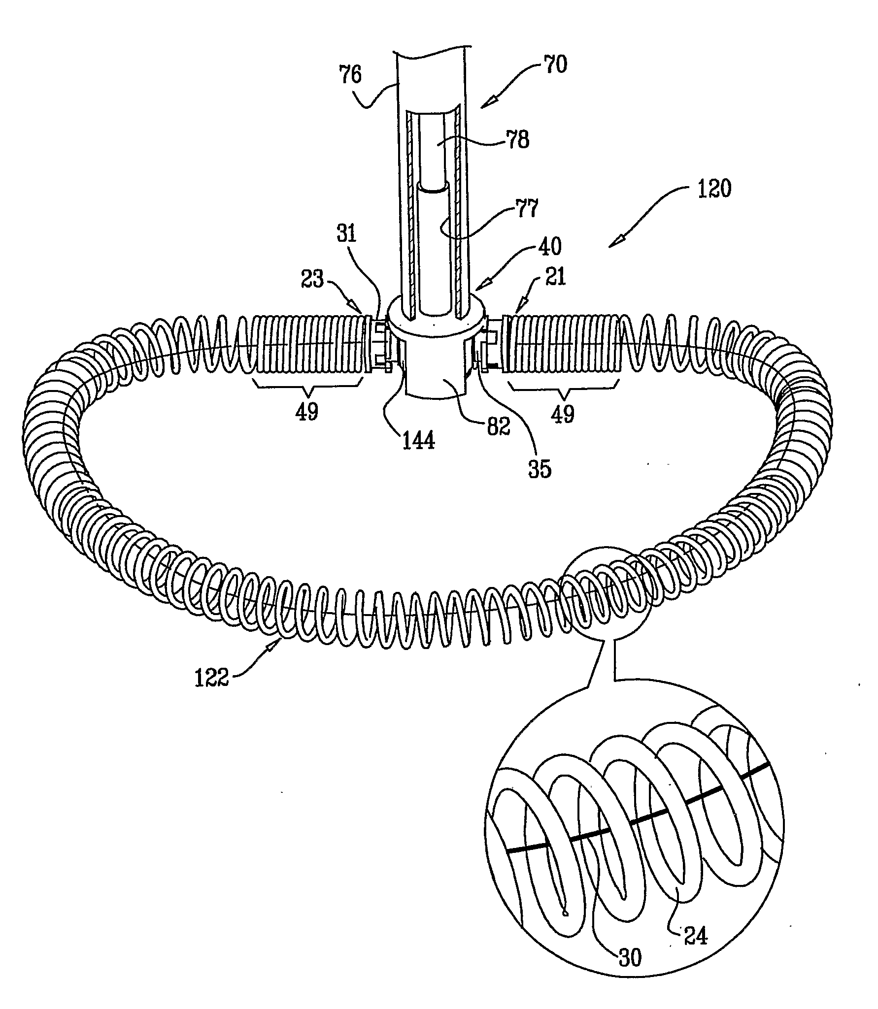
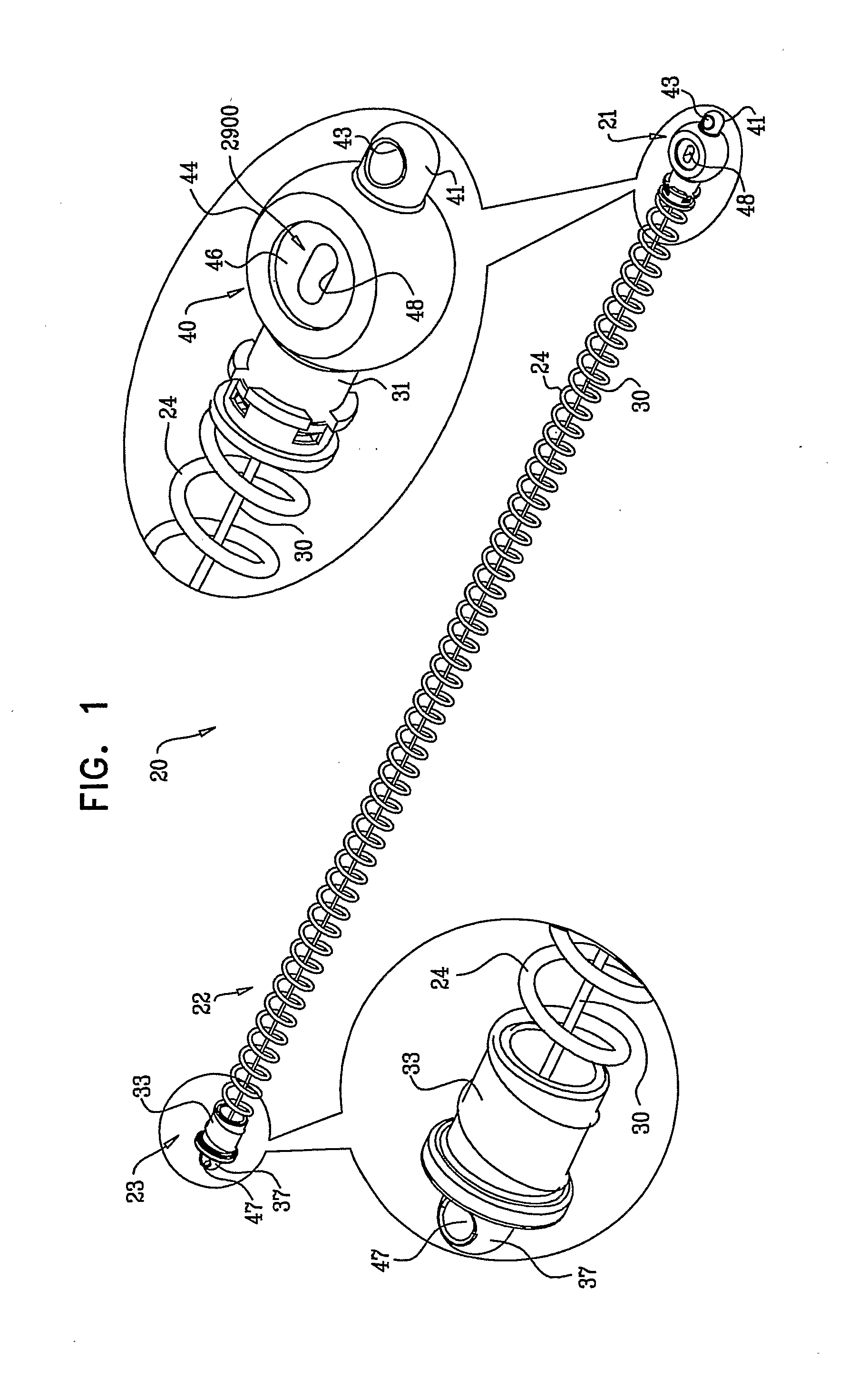
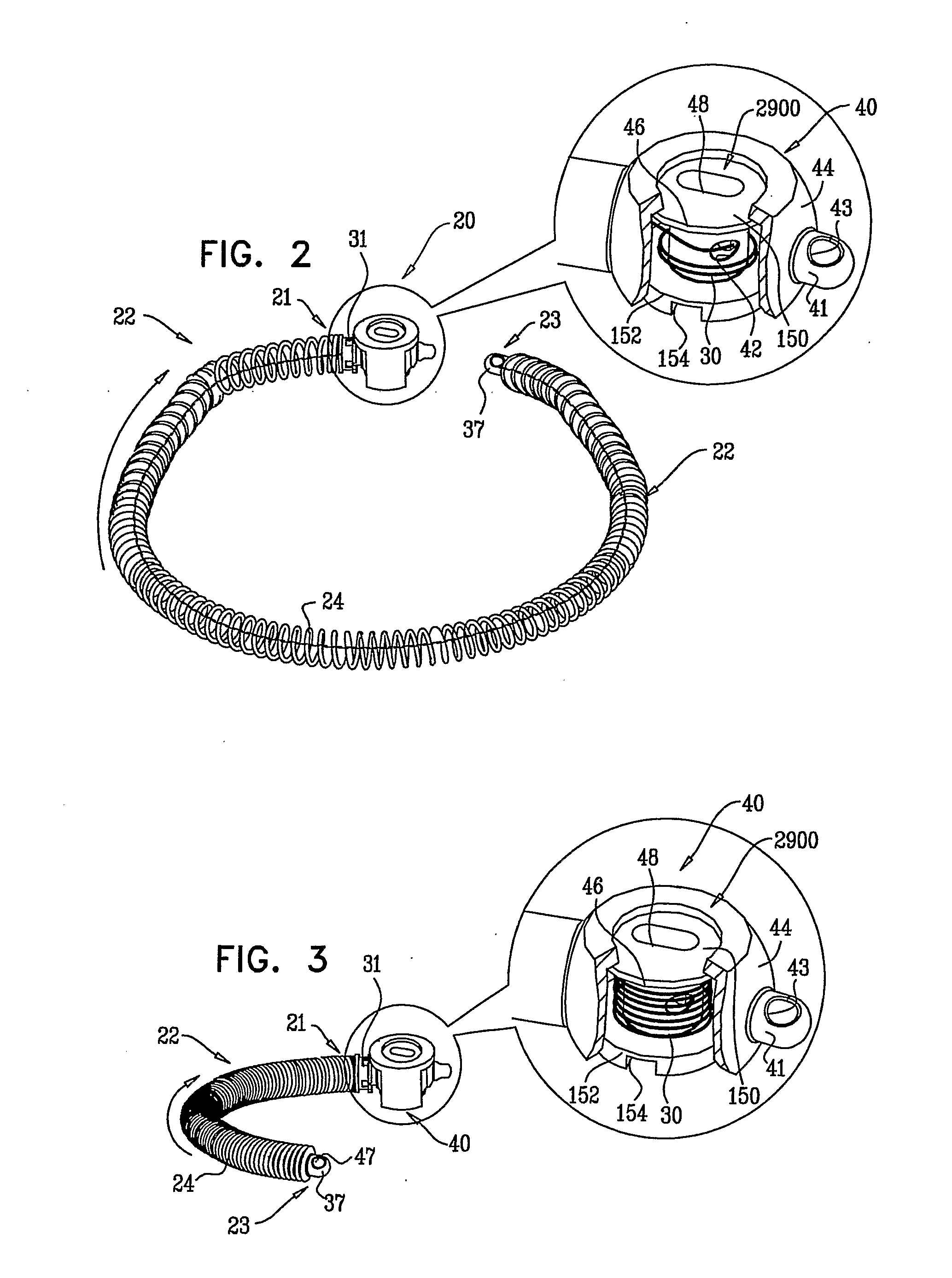
[0050]In some applications of the present invention, apparatus is provided comprising an adjustable annuloplasty structure configured to repair a dilated mitral valve of a patient. At least a portion of the annuloplasty structure comprises a flexible, longitudinally-compressible segment (e.g., coiled structures, stent-like struts, or a braided mesh). The annuloplasty structure is shaped to define a lumen thereof that houses a flexible member, e.g., a contracting wire. The annuloplasty structure comprises a contracting mechanism which facilitates contracting of the annuloplasty structure. The contracting mechanism comprises a spool to which a first end of the flexible member is coupled. Typically, a second end of the flexible member is not coupled to the spool, but rather is coupled to a portion of the annuloplasty structure.
[0051]In some applications of the present invention, the annuloplasty structure is shaped to provide an adjustable partial annuloplasty structure. In these appli...
PUM
 Abstract
Description
Claims
Application Information