Amplification-Based Cardiac Assist Device

a technology of assist device and amplifier, which is applied in the direction of blood pump, other medical devices, therapy, etc., can solve the problems of diaphragm inflation and tube deformation, and achieve the effect of shortening the effective length of the band

Inactive Publication Date: 2008-03-13
BAR ELI +2
View PDF48 Cites 60 Cited by
  • Summary
  • Abstract
  • Description
  • Claims
  • Application Information

AI Technical Summary

Benefits of technology

[0033]The hydraulic system was placed around a latex heart model. The system was tested at physiological heart rates, pressures and flow rates. Power consumption was measured. DC power of approximately 10 Watts generated reasonable “cardiac” output from the passive latex heart, during a short test period. This power consumption was achieved with the device wet, in order to reduce friction.
[0060]In an embodiment, the apparatus includes a diastole-supporting mechanism, adapted to store energy from the pump during systole, and to release the energy during diastole in a manner that facilitates application of an outwardly-directed force to an epicardial surface of the heart during diastole.
[0125]a band, an effective length of the band being adapted to surround a portion of the heart and to shorten responsive to the control unit driving the shape-changing members to change shape, whereby to enhance contraction of the heart.
[0134]In an embodiment, the control unit is adapted to drive fluid into the cylinder to cause the effective length of the band to shorten.
[0135]In an embodiment, the control unit is adapted to draw fluid out of the cylinder to cause the effective length of the band to shorten.

Problems solved by technology

The tube is connected to a source of fluid under pressure, the admission of which causes deformation of the tube and consequent inflation of the diaphragm.

Method used


Image

  • Amplification-Based Cardiac Assist Device
  • Amplification-Based Cardiac Assist Device
  • Amplification-Based Cardiac Assist Device

Examples


Embodiment Construction

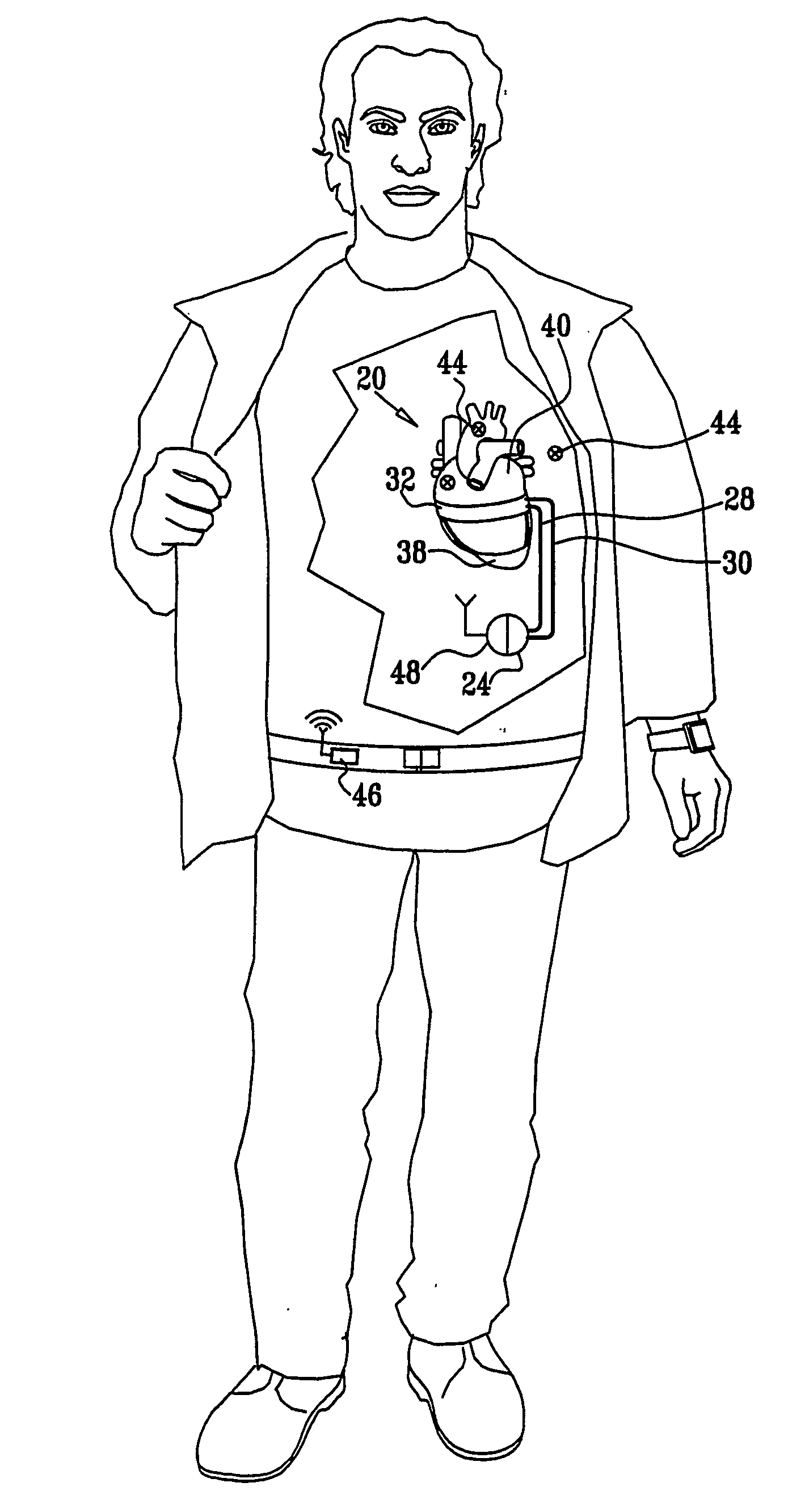
[0178]FIG. 1 is a schematic illustration of a system 20 for supporting the functioning of a heart 40 of a patient, in accordance with an embodiment of the present invention. System 20 comprises a sleeve 32, which surrounds one or more chambers of heart 40, and a control unit 24, which actuates the sleeve to apply a compressive force to heart 40. Control unit 24 is in operational communication with sleeve 32 via one or more electrical leads 28 and / or one or more tubes 30. For example, control unit 24 may comprise a pump that drives a fluid (i.e., a liquid or a gas) through tubes 30, into or out of sleeve 32, whereby to cause contraction of the sleeve around the heart and a resultant enhancement of cardiac output. Alternatively or additionally, control unit 24 drives a current through leads 28, whereby to cause contraction of the sleeve around the heart and a resultant enhancement of cardiac output. For some applications, control unit 24 receives signals, wirelessly or through leads 2...


PUM


Abstract

Apparatus (20) is provided for compressing at least one ventricle of a heart (40). The apparatus includes a plurality of inflatable elements (64) and a pump (24) in fluid communication with the inflatable elements. At least one band (68) is in mechanical communication with the inflatable elements. A portion of the band is adapted to be placed around at least a portion of the heart in mechanical communication with the portion of the heart. The inflatable elements are arranged such that when the inflatable elements are inflated by the pump, the inflatable elements apply more force to the heart via shortening of the portion of the band than via expansion of the inflatable elements against the heart.

Description

CROSS-REFERENCES TO RELATED APPLICATIONS[0001]The present patent application claims priority from:[0002](a) U.S. Provisional Patent Application 60 / 511,548 to Kornowski and Bar, filed Oct. 15, 2003, entitled, “Dynamic external myocardial stent to enhance left ventricular contractility in heart rate patients,” and[0003](b) U.S. Provisional Patent Application 60 / 599,176 to Rousso and Bar, filed Aug. 4, 2004, entitled, “Balloon based cardiac assist device.”[0004]Both of these applications are incorporated herein by reference.BACKGROUND OF THE INVENTION[0005]Congestive Heart Failure (CHF) occurs when the heart is unable to meet the hemodynamic needs of the body. The contractility of the heart is reduced, and thus the stoke volume and cardiac output are reduced. Cardiac assist devices assist the heart to pump blood in order to meet the body's demand.[0006]The following references may be relevant to the practice of some embodiments of the present invention:[0007]U.S. Pat. No. 6,626,821 to ...

Claims


Application Information

Patent Timeline
Patent Type & Authority Applications(United States)
IPC IPC(8): A61M1/12A61BA61M60/191A61M60/289A61M60/468A61M60/484A61M60/486A61M60/495A61M60/515A61M60/531A61M60/863A61M60/873A61M60/876A61M60/878
CPCA61M1/106A61M1/1058A61M1/1055A61M1/1068A61M2205/33A61M2205/3303A61M2205/8243A61M60/484A61M60/289A61M60/878A61M60/531A61M60/191A61M60/486A61M60/495A61M60/468A61M60/863A61M60/515A61M60/873A61M60/876
Inventor BAR, ELIROUSSO, BENNYKORNOWSKI, RAN
Owner BAR ELI
Why Eureka
Try Eureka