PLM-supportive CAD-CAM tool for interoperative electrical & mechanical design for hardware electrical systems

a technology of hardware electrical systems and cam tools, which is applied in the field of computer-aided design (cad) and computer-aided manufacturing (cam) tools, can solve the problems of affecting the quality of hardware electrical systems, and affecting the delivery of products to market, so as to reduce the organizational cost of training time, increase the flexibility and value of plm-supportive, and save expensive human labor

Inactive Publication Date: 2005-04-14
CHERNYAK ALEX H +3
View PDF6 Cites 262 Cited by
  • Summary
  • Abstract
  • Description
  • Claims
  • Application Information

AI Technical Summary

Benefits of technology

[0024] The PLM System will manage the design considerations which cross the boundaries between projects, or even between organizational groupings (at the same level), or even across organizational boundaries (i.e. across related or even unrelated companies). Such would include, for example, the maintenance of standards, coordination of design changes or accommodations; management of resources and timing; documentation unification, tracking, coordination, and control; Engineering Change Order processing; and related manufacturing efforts (including timing, distribution, purchasing, ordering, delivery scheduling, and timing). The PLM System is an explicit tool that not only recognizes that any HES is both a cooperative and competitive effort and provides means to maximize the former approach, which grants an advantage in lowering the frictional and information-limited costs of the latter approach to product design, production, and life-cycle.

Problems solved by technology

First, even a ‘simple’ HES design requires mastery and control over an enormous variety and quantity of data, which, if inaccurate, results in avoidable inefficiencies and delays delivery of products to market.

Method used


Image

  • PLM-supportive CAD-CAM tool for interoperative electrical & mechanical design for hardware electrical systems
  • PLM-supportive CAD-CAM tool for interoperative electrical & mechanical design for hardware electrical systems
  • PLM-supportive CAD-CAM tool for interoperative electrical & mechanical design for hardware electrical systems

Examples


Embodiment Construction

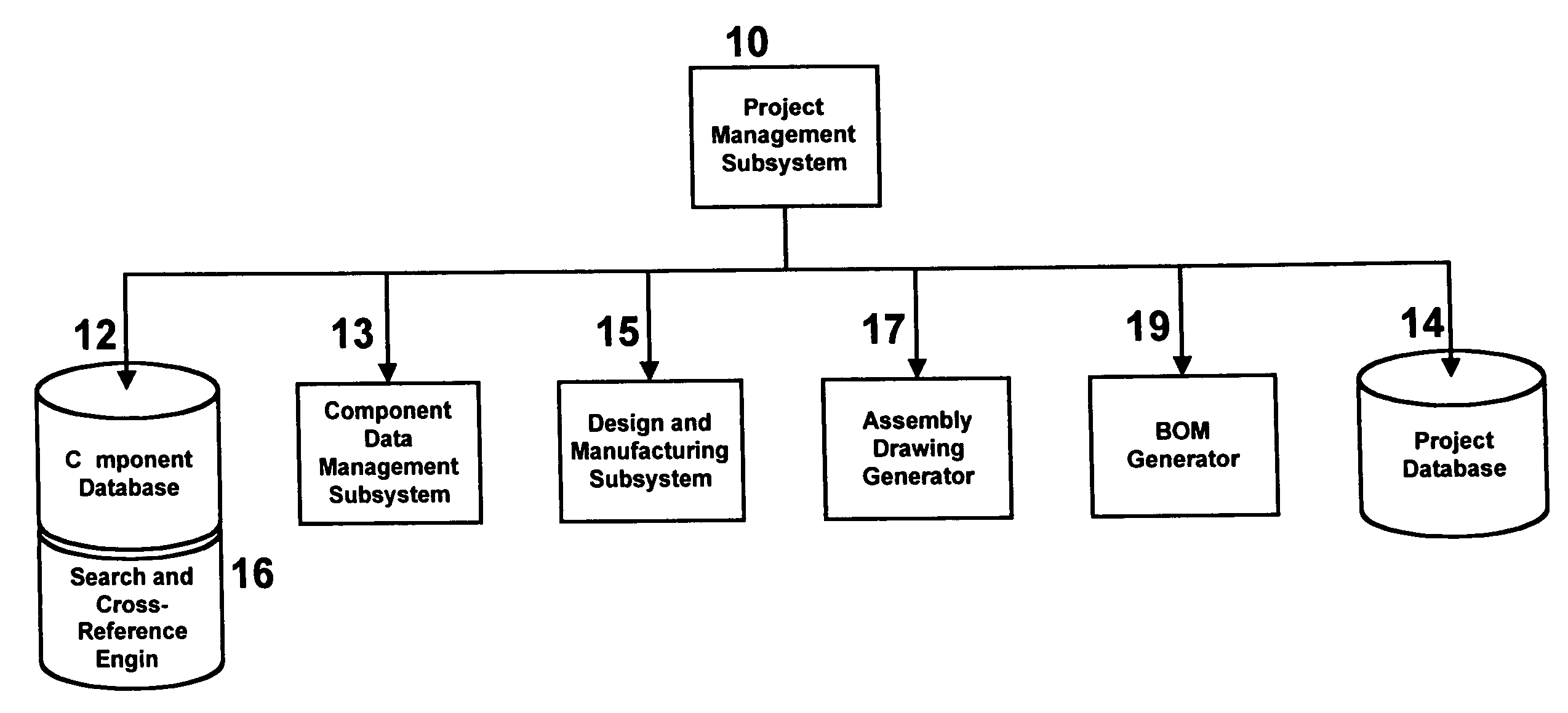
[0071] The invention disclosed in this specification and its supporting papers is a software, PLM-supportive, Computer-Aided-Design and Computer-Aided-Manufacturing tool, which in the best embodiment herein is for multi-disciplinary Hardware Electrical Systems (HES). Among the objectives of the invention are: (1) automating the design process for HES; (2) reducing the costs for designing, and for manufacturing, HES; (3) significantly streamlining and integrating the design and manufacture of HES with that of the connected separate assemblies into an integrated system which includes for each HES design systemic testing, simulation, and validation; and (4) making more efficient the entire lifecycle from conception to manufacture to redesign and adaptation to reuse in more complex assemblages for complex, multi-disciplinary products. There are multiple parts to the PLM-supportive, CAD-CAM tool, which are described herein.

Summary Description of the Subordinate Elements

[0072] As stated...


PUM


Abstract

This invention is a tool for computer-aided design, computer-aided manufacturing forming a Project Management System, comprising: (1) a Component Database; (2) a Component Data Management System; (3) a Design and Manufacturing System; (4) an Assembly Drawing Generator; (5) a Bill of Materials Generator; and, (7) a Project Database. The Project Manager tracks the process and actions, recording and supervising version and change order compliance and task completion, from the start through verification of a production-ready finished version. Each project uses a master workbench. On it design specifications are entered for each subassembly element and connector. Then the user consults the Component Database using a Search and Cross Reference engine for components meeting those design specifications, until a constraint-satisfying design is completed. The tool generates a Bill of Materials, Assembly Drawings, and process records for the project in process.

Description

BACKGROUND OF THE INVENTION [0001] In the past score of years Computer-Aided Design (CAD) and Computer-Aided Manufacturing (CAM) tools have been created; some for particular manufactured components (such as a computer chip), some for complex components which incorporate sub-assemblies of electrical components (such as printed circuit boards, computer motherboards or power supplies), and some for discrete pin-to-pin interconnections between separate electrical component circuits. Extremely powerful and elaborate tools have also been created for individual semiconductor-based, integrated-circuit chips' logic circuit design, layout, and manufacturing; similarly, powerful, three-dimensional visualization, rendering, and supportive tools for designing complex-shaped mechanical parts and assemblies have been created. Companies now focus on increasing the density and complexity of particular manufactured components to increase the value-added aspect of their business. [0002] Most of these ...

Claims


Application Information

Patent Timeline
Patent Type & Authority Applications(United States)
IPC IPC(8): G06F17/50G06F19/00
CPCG06F17/50G06F2217/36G06F2217/04G06F30/00G06F2111/02G06F2113/16
Inventor CHERNYAK, ALEX H.GELMAN, BENJAMINSAVRANSKY, MICHAELCHERKIS, YANUSH
Owner CHERNYAK ALEX H
Why Eureka
Try Eureka