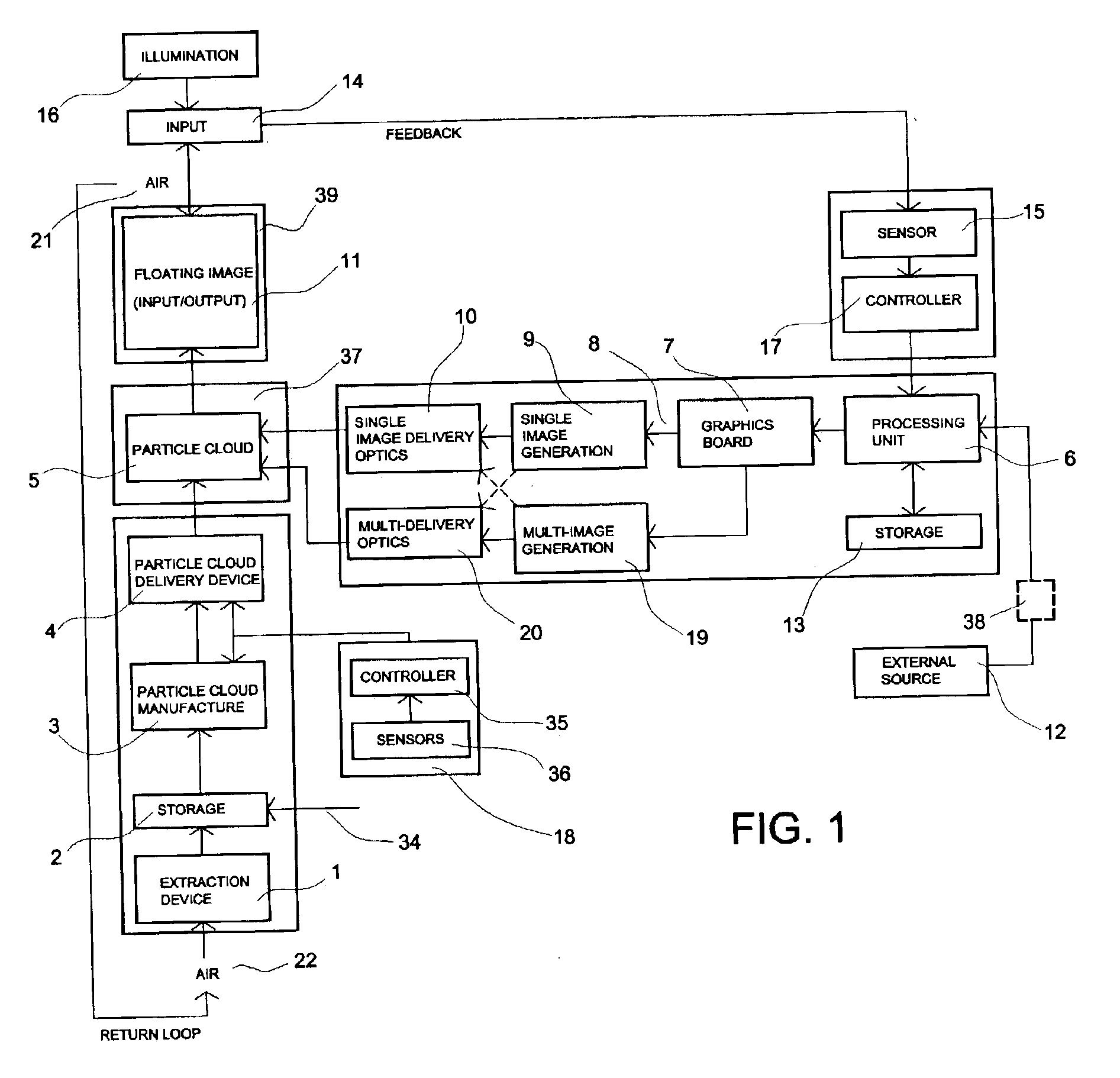
Furthermore, any physical intrusion, occurring spatially within the particle cloud image region, is captured by a detection system and the intrusion such as a
finger movement, enables information or image to be updated and interacted with in real-time. This input / output (I / O) interface provides a novel display and computer interface, permitting the user to select, translate and manipulate free-space floating visual information beyond the physical constraints of the device creating the image. This invention provides a novel
augmented reality platform for displaying information coexisting spatially as an
overlay within the real physical world. The interactive non-
solid free floating characteristics of the image allow the display space to be physically penetrable for efficient concurrent use between physical and ‘virtual’ activities in multi-tasking scenarios including collaborative environments for military planning, conferencing, and
video gaming, as well as presentation displays for advertising and point-of-sales presentations.
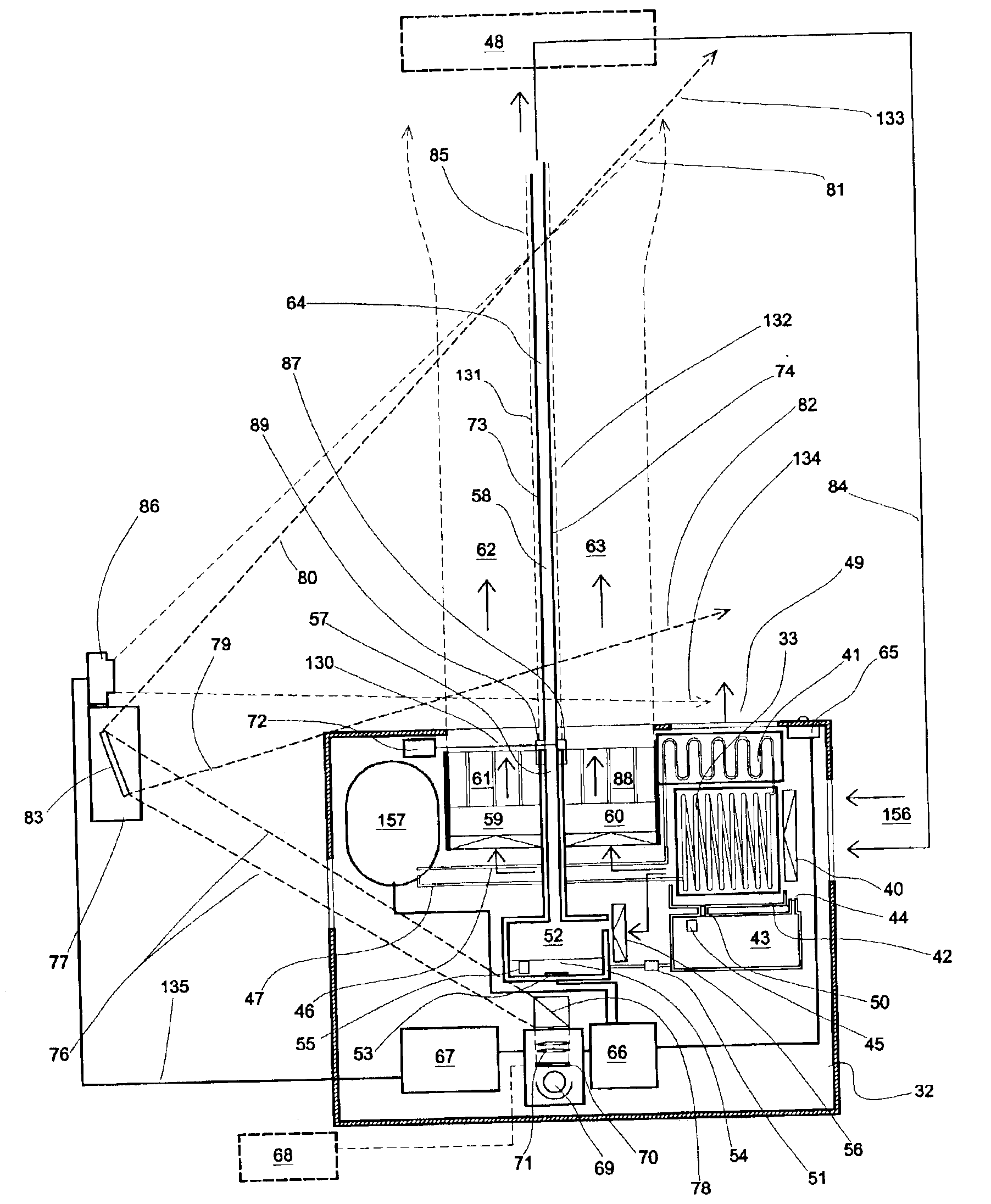
The invention comprises significant improvements over existing non-physical screens to display clear images, independent of the pure laminar screen found in the prior art, by functioning with non-laminar, semi-laminar and turbulent particle clouds. Novel advancements to the microenvironment deployment method by means of a multiple stage
equalization chamber and baffles generate an even laminar
airflow reducing pressure gradients and boundary layer friction between the particle cloud and the surrounding air. Furthermore, the electronic environmental management control (EMC) attenuates particle cloud density by controlling the amount of
particulates generated and ejected in conjunction with the particle cloud exit velocity, thereby ensuring an invisible to near-invisible screen. This delicate balance of the particle cloud density and illumination intensity was not possible in the prior art and therefore the cloud was either highly visible or too low of a density to generate a bright image. Further advancements to both an improved
projection system improve viewing angle limitations inherent with prior art such as fluttering caused by turbulence within the screen. Furthermore, the invention's self-contained and self-sustaining system is capable of producing a constant
stream of cloud particles by condensing
moisture from the surrounding air, thereby allowing the system to operate independently without affecting the general
operating environment. Furthermore, the invention incorporates interactive capabilities, absent in prior art.
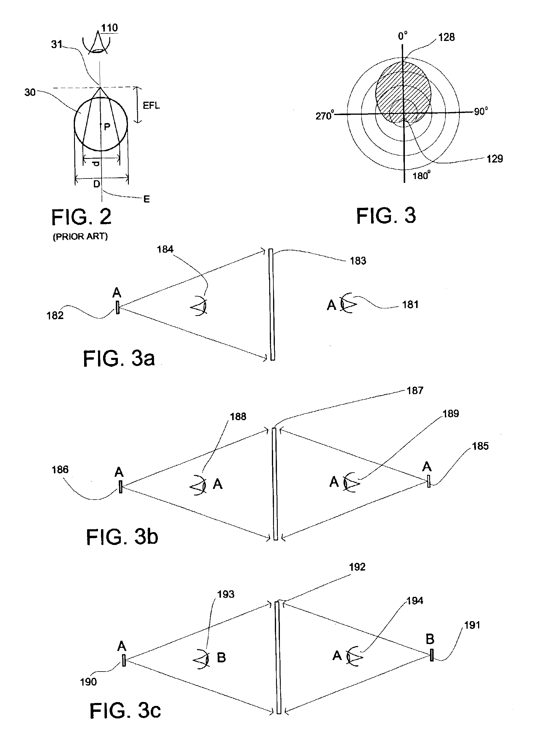
The multiple projection source of this invention has the capacity to produce multi-imaging; were discrete images projected from various sources can each be viewed from different locations. This allows a separate image to be generated and viewed independently from the front and rear of the display, for use as example in video-gaming scenarios, where opposing players observe their separate “points of view” while still being able to observe their opponent through the image. In addition, the multisource projection redundancy mitigates
occlusion from occurring, such as in the prior art, where a person standing between the projection source and the screen, blocks the image from being displayed.
By projecting from solely one side, the display can also serve as a one-way privacy display where the image is visible from one side and mostly transparent from the other side, something not possible with conventional displays such as television,
plasma or computer CRT's and LCD monitors. Varying the projected illumination intensity and cloud density can further attenuate the image transparency and
opacity, a function not possible with existing displays. Furthermore, since the image is not contained within a “physical box” comprising a front, flat physical screen, such as in a conventional display, the image is capable of taking on numerous geometries that are not limited to a flat plane. Furthermore, the dimensions of the image are substantially larger than the dimensions of the device creating the image since the image is not constrained to a physical
enclosure such as a convention LCD or CRT. The display can also take on varying geometric shapes, generating particle cloud surfaces other than a flat plane, such as cylindrical or curved surfaces. For these particle cloud types adaptive or corrective
optics allow compensate for variable focal distances for the projection.
Applications for this technology are wide-
ranging, since the displayed image is non-physical and therefore unobtrusive. Imaged information can be displayed in the center of a room, where people or objects can move through the image, for use in teleconferencing, or can be employed as a ‘virtual’ heads-up display in a medical
operating theater, without interfering with
surgery. The system of this invention not only frees up space where a conventional display might be placed, but due to its variable
opacity and multi-viewing capability, allows the device to be centered around multiple parties, to freely view, discuss and interact collaboratively with the image and each other. The device can be hung from the ceiling, placed on walls, on the floor, concealed within furniture such as a
desk, and project images from all directions, allowing the image can be retracted when not in use. A scaled down version allows portable devices such as PDA's and
cell phones to have ‘virtual’ large displays and interactive interface in a physically small
enclosure.

